
Sheet feeder device and image forming apparatus

a feeder device and image forming technology, applied in the direction of thin material processing, instruments, article separation, etc., can solve the problems of paper jam, document sheets to be fed askew or to make thin document sheets wrinkle,

Inactive Publication Date: 2008-12-16
SHARP KK
View PDF7 Cites 12 Cited by
  • Summary
  • Abstract
  • Description
  • Claims
  • Application Information

AI Technical Summary

Benefits of technology

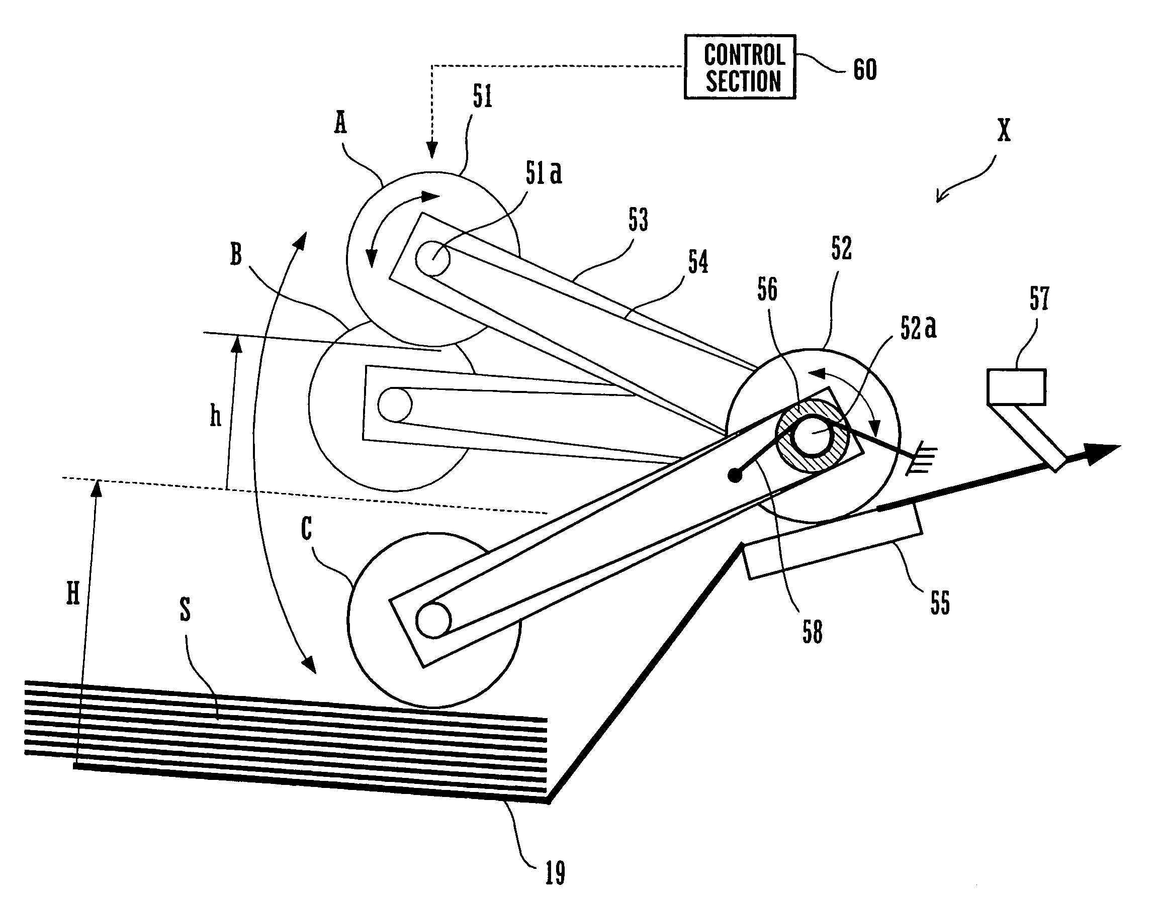
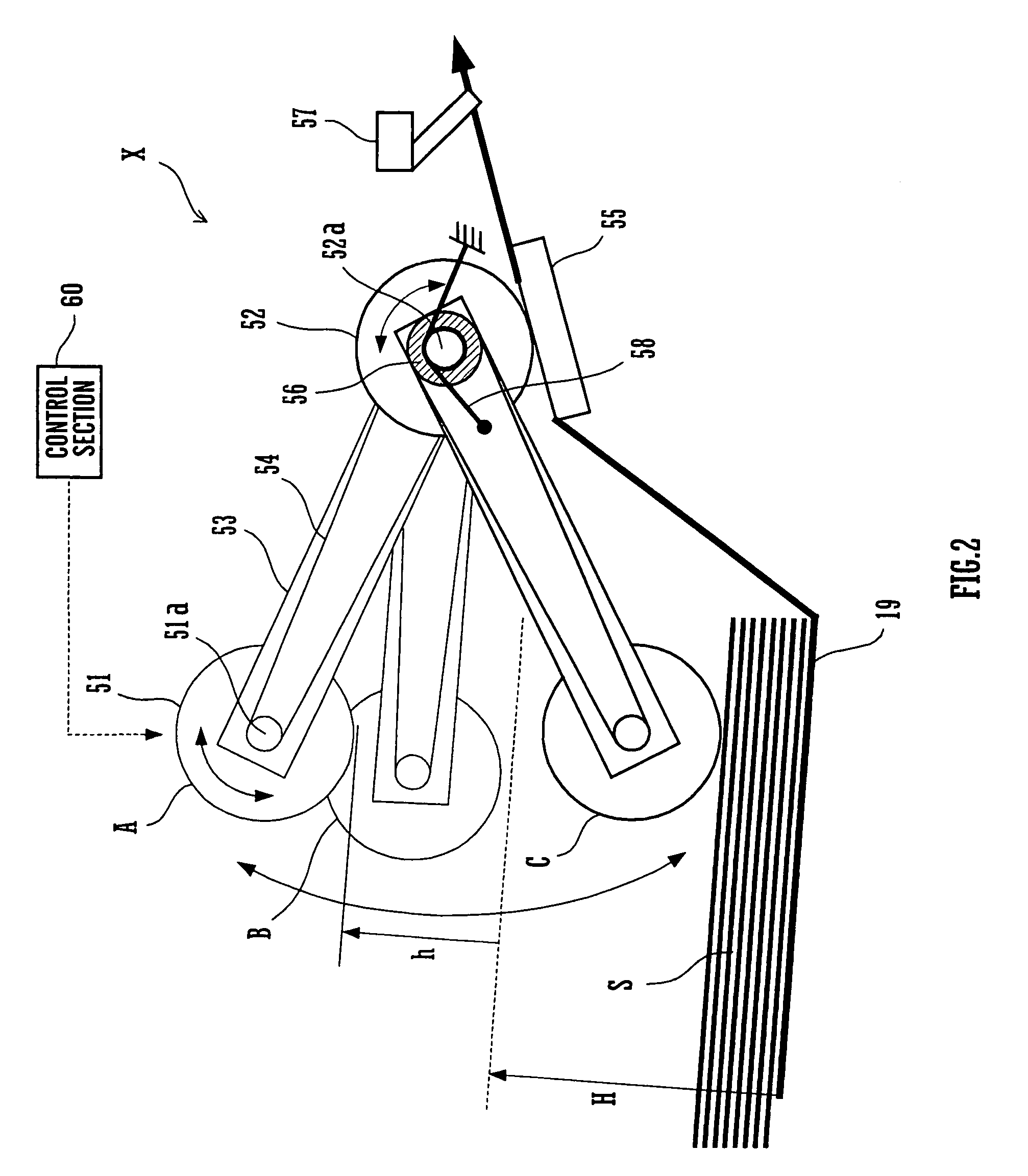
The present invention provides a sheet feeder device that can feed sheets with reduced spacing between adjacent sheets without increasing the sheet transport speed. The device includes a pick-up roller that can abut against and separate away from a sheet, and a pick-up roller driving section that can position the pick-up roller into three stepwise positions including a retracted position, a sheet feed position, and a standby position. The pick-up roller driving section can position the pick-up roller into the standby position during a period from a point in time just after feeding of one sheet to a point in time just before feeding of a succeeding sheet in a series of sheets. This arrangement can minimize the range of motion of the feed means, reducing the spacing between adjacent sheets under feeding. The pick-up roller driving section includes an arm member, a separating roller, and a rotary power transmission section. The device also includes a clutch and bias means to position the pick-up roller into the standby position. The technical effects of the invention are to improve the efficiency and accuracy of sheet feeding in image forming apparatuses.

Problems solved by technology

However, the prior art described in this patent publication involves a problem that the increased document sheet transport speed is likely to cause document sheets to be fed askew or to make thin document sheets become wrinkled.
In addition, when the feed path is curved, the increased transport speed is likely to cause a paper jam to occur.

Method used


Image

  • Sheet feeder device and image forming apparatus
  • Sheet feeder device and image forming apparatus
  • Sheet feeder device and image forming apparatus

Examples


Embodiment Construction

[0022]Hereinafter, embodiments of the present invention will be described in detail with reference to the drawings. It should be noted that these embodiments are only illustrative of the present invention and hence should not be construed to limit the technical scope of the present invention.

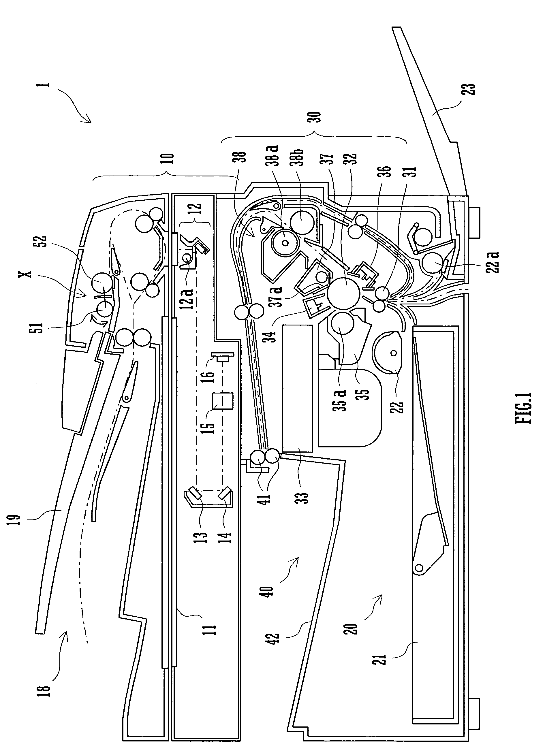
[0023]FIG. 1 is a sectional side elevational view schematically showing the construction of an image forming apparatus provided with a document feeder device X according to an embodiment of the present invention; FIG. 2 is a schematic side elevational view of the document feeder device X according the embodiment of the present invention; and FIG. 3 is a flowchart of the procedural steps performed by the document feeder device X.

[0024]Image forming apparatus 1 provided with document feeder device X according to an embodiment of the present invention will be described with reference to the sectional side elevational view at FIG. 1.

[0025]The image forming apparatus 1 has printing modes including a ...


PUM


Abstract

A sheet feeder device is provided with a pick-up roller driving section which is operative to position the pick-up roller into a retracted position spaced a predetermined distance apart from a stack of document sheets on a document tray before and after the operation for feeding the series of document sheets, into a sheet feed position in which the pick-up roller abuts against the stack of document sheets for feeding the document sheets at an occasion of feeding of each of the document sheets in the operation for feeding the series of document sheets, and into the standby position above and close to the height of a stack of a maximum load number of document sheets carried on the document tray during a period from a point in time just after feeding of one sheet to a point in time just before feeding of a succeeding sheet.

Description

CROSS REFERENCE[0001]This nonprovisional application claims priority under 35 U.S.C. §119(a) on Patent Application No. 2003-185124 filed in Japan on Jun. 27, 2003, the entire contents of which are hereby incorporated by reference.BACKGROUND OF THE INVENTION[0002]The present invention relates to a sheet feeder device provided in an image forming apparatus such as a printer, facsimile apparatus or copying machine for feeding such sheets as document sheets or recording sheets to the image forming apparatus. The present invention also relates to an image forming apparatus provided with such a sheet feeder device.[0003]In an image forming apparatus such as a copying machine or a printer, a given sheet feeder device feeds such sheets as document sheets or recording sheets from a sheet tray such as a document tray or a paper feed tray toward the image forming section.[0004]Such a sheet feeder device picks up sheets one by one by rotating a given pick-up roller pressed against the uppermost...

Claims


Application Information

Patent Timeline
Patent Type & Authority Patents(United States)
IPC IPC(8): B65H3/06G03G15/00
CPCB65H3/0615B65H3/0669B65H3/0684
Inventor MORIMOTO, YASUMASANISHIZATO, YOSHIYUKITAMEHIRA, MASATOOKAMOTO, SYOUTARONAGAI, YOSHIYUKI
Owner SHARP KK
Learn More