Intake system

a technology of intake system and intake chamber, which is applied in the direction of combustion air/fuel air treatment, machines/engines, propulsion parts, etc., can solve the problems of reducing the intake efficiency, and achieve the effect of enhancing the intake efficiency and reducing the size of the air cleaner cas

Active Publication Date: 2008-12-16
HONDA MOTOR CO LTD
View PDF11 Cites 11 Cited by
  • Summary
  • Abstract
  • Description
  • Claims
  • Application Information

AI Technical Summary

Benefits of technology

[0010]It is an object of an embodiment of the present invention to improve an intake system and thereby to enhance a reduction in the size of an air cleaner case and to provide an enhancement in the intake efficiency.

Problems solved by technology

Or, in the case where the front opening portion of the air cleaner case is restricted to a predetermined size, the outer shape of the air cleaner element is smaller by the mount portion, so that the opening portion is also smaller, thus resulting in a reduction in the intake efficiency.

Method used


Image

  • Intake system
  • Intake system
  • Intake system

Examples


Embodiment Construction

[0030]A best mode for carrying out the present invention will be described below, based on the accompanying drawings. The drawings are to be viewed according to the posture of symbols.

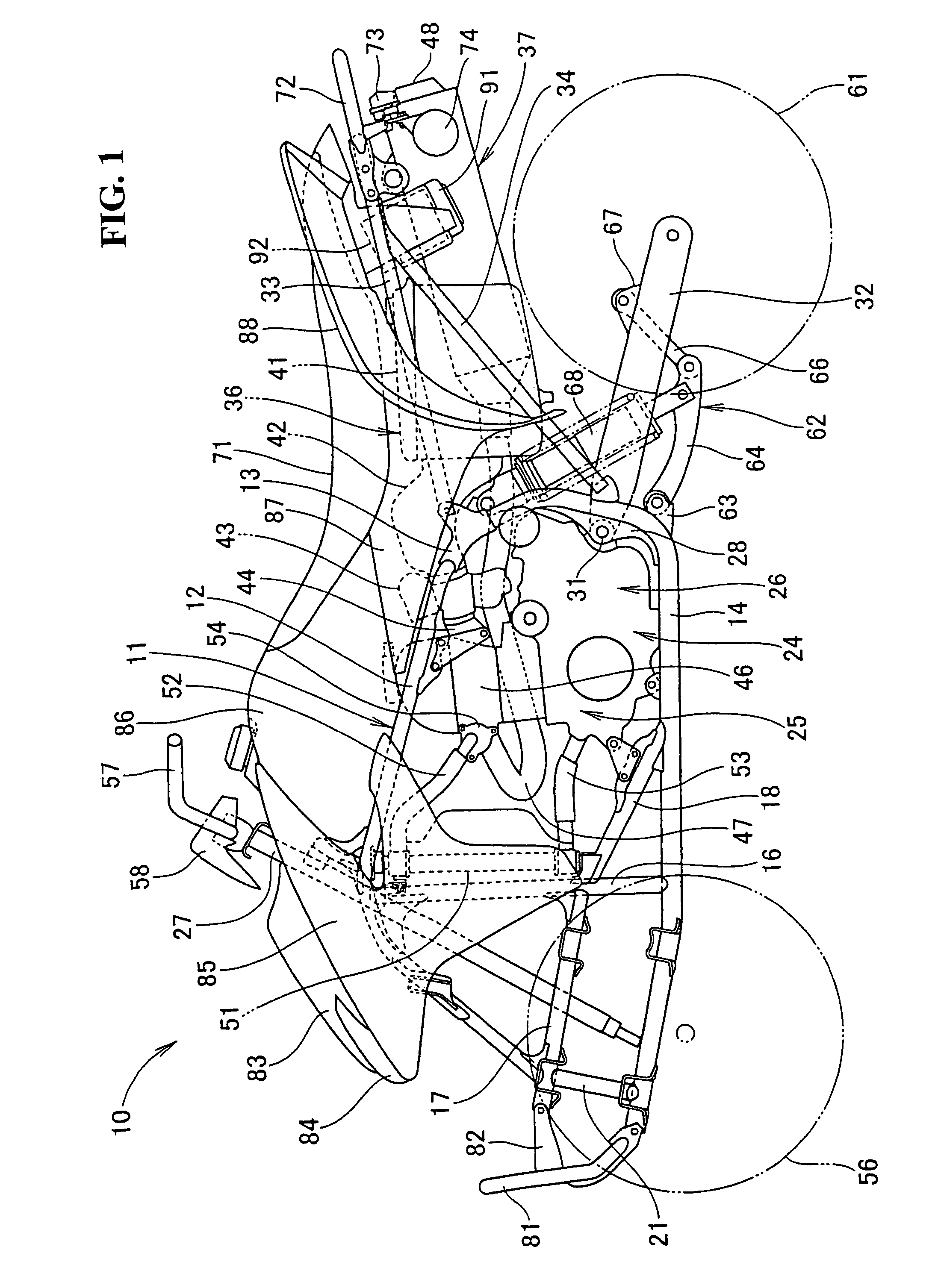
[0031]FIG. 1 is a side view of a saddle ride type vehicle including an intake system according to the present invention. The saddle ride type vehicle 10 is an all-terrain vehicle which includes a vehicle body frame 11, and the vehicle body frame 11 is composed of a left-right pair of main pipes 12 that are roughly V-shaped in side view (of members in a left-right pair, only the one on the viewer's side is shown here and hereinafter). A left-right pair of lower pipes 14 are connected to the main pipes 12 respectively through a connection member 13. The vehicle body frame 11 is further composed of a left-right pair of down pipes 16 that extend roughly in a vertical direction between the main pipe 12 and the lower pipe 14, a left-right pair of front reinforcing pipes 17 mounted, respectively, to the front...


PUM

PropertyMeasurementUnit
diameteraaaaaaaaaa
shapeaaaaaaaaaa
metallicaaaaaaaaaa

Abstract

An intake system with an air cleaner case that is reduced in size with an enhancement in intake efficiency. A tubular tip end portion of a connecting tube provides a connection between the carburetor side and the air cleaner case with the tubular tip end portion being disposed in the air cleaner case. A tubular opening end portion is provided in an air cleaner element contained in the air cleaner case for connecting to the tubular tip end portion of the connecting tube. A large diameter portion is provided in a frame member serving as a core of the air cleaner element for supporting the tubular end portion and the tubular opening end portion in a condition wherein the tubular tip end portion and the tubular opening end portion are fitted to each other. The large diameter portion is larger in diameter than any other portion of the frame member.

Description

CROSS-REFERENCE TO RELATED APPLICATIONS[0001]The present non-provisional application claims priority under 35 USC 119 to Japanese Patent Application No. 2004-284323 filed on Sep. 29, 2004 the entire contents thereof is hereby incorporated by reference.BACKGROUND OF THE INVENTION[0002]1. Field of the Invention[0003]The present invention relates to an improvement in an intake system.[0004]2. Description of Background Art[0005]A conventional intake system is known wherein a filter is pressed against an inner wall portion of a cleaner case by a filter holder so as to fix the filter to the cleaner case. See, for example, Japanese Patent Laid-open No. 2003-56420. In addition, the present inventor has provided a conventional intake system in which a base for supporting an air cleaner element is attached to a front surface of an air cleaner case by small screws. See, for example, Japanese Patent Laid-open No. 2003-56420.[0006]As illustrated in FIG. 2(B) of Japanese Patent Laid-open No. 2003...

Claims


Application Information

Patent Timeline
Patent Type & Authority Patents(United States)
IPC IPC(8): B01D46/00B62J99/00
CPCB62K5/01F02M35/024F02M35/10144F02M35/162F02M35/0203Y02T10/14Y02T10/12
Inventor OSHIMA, TADASHI
Owner HONDA MOTOR CO LTD
Why Eureka
Try Eureka