Wide-angled image display system for automobiles

a wide-angle image and display system technology, applied in the field of wide-angle image display systems, can solve the problems of large 747 jets approaching the landing strip in an airport with landing gear down always appearing awfully slow, misguided sense, and 747 jets going awfully slow at landing, so as to improve consumer safety

Inactive Publication Date: 2008-12-16
XIE YILING
View PDF4 Cites 12 Cited by
  • Summary
  • Abstract
  • Description
  • Claims
  • Application Information

AI Technical Summary

Benefits of technology

[0007]By using a pseudo-car image (“PCI”) logic, present invention incorporates the use of multiple cameras to produce a wide-angled view, while eliminating the illusion described previously, to enhance consumer safety.

Problems solved by technology

For example, a large 747 jet approaching the landing strip in an airport with landing gear down always seems awfully slow; whereas a small propeller airplane seems to zoom by like a bullet when it is ready to land.
Therefore people have the misguided sense that the 747 jet goes awfully slow at landing, when in reality it goes faster than a small propeller airplane just about to land.
Drivers oftentimes misjudged the speed of a big truck approaching from behind, especially when the drivers made that misjudgment from one of the three rearview mirrors, whose functions are limited by their blind spots.

Method used


Image

  • Wide-angled image display system for automobiles
  • Wide-angled image display system for automobiles
  • Wide-angled image display system for automobiles

Examples


Embodiment Construction

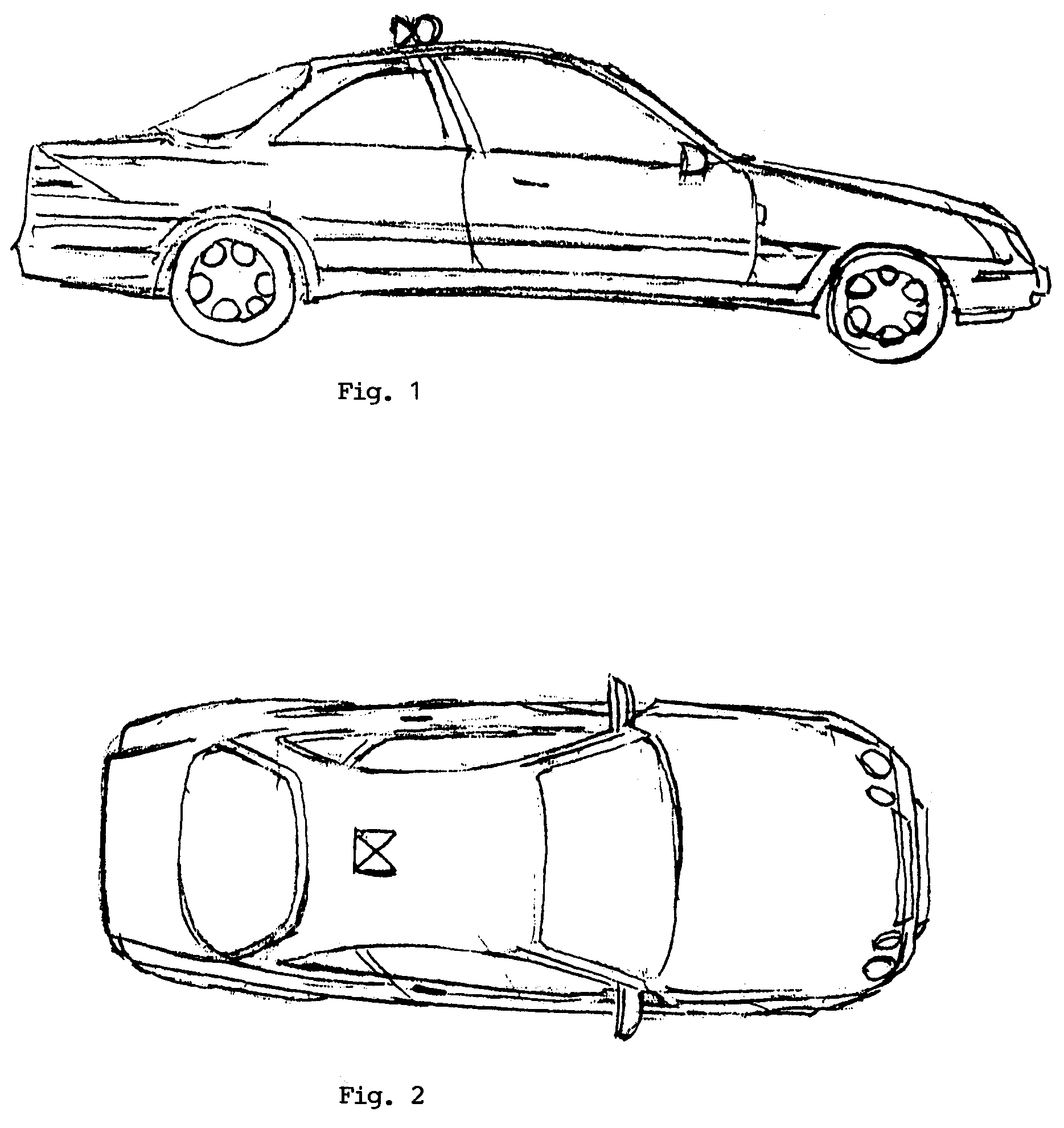
[0016]In FIG. 1, three cameras are mounted on top of a vehicle. This side view shows only the right and center camera.

[0017]FIG. 2, top-down view of the three cameras are shown. Although present embodiment shows the cameras to be on top, they can be installed on brink of the trunk, or near the C-pillar of a vehicle, as long as the viewing angles are not obstructed by the positions of the installation.

[0018]Depending on how and where the cameras are mounted, a small motor may be added to the left or right camera so that when the driver engages the turn signal of the car, the left / right camera will turn a limited angle (10 degrees, for example) to widen the coverage area towards which the car is about to turn.

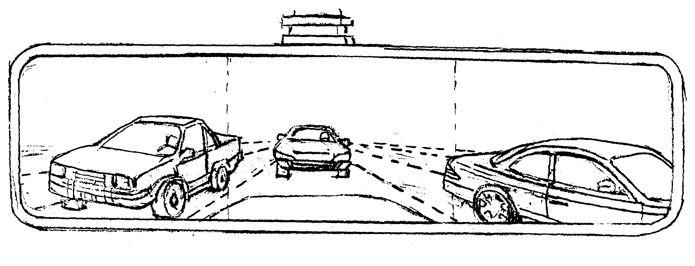
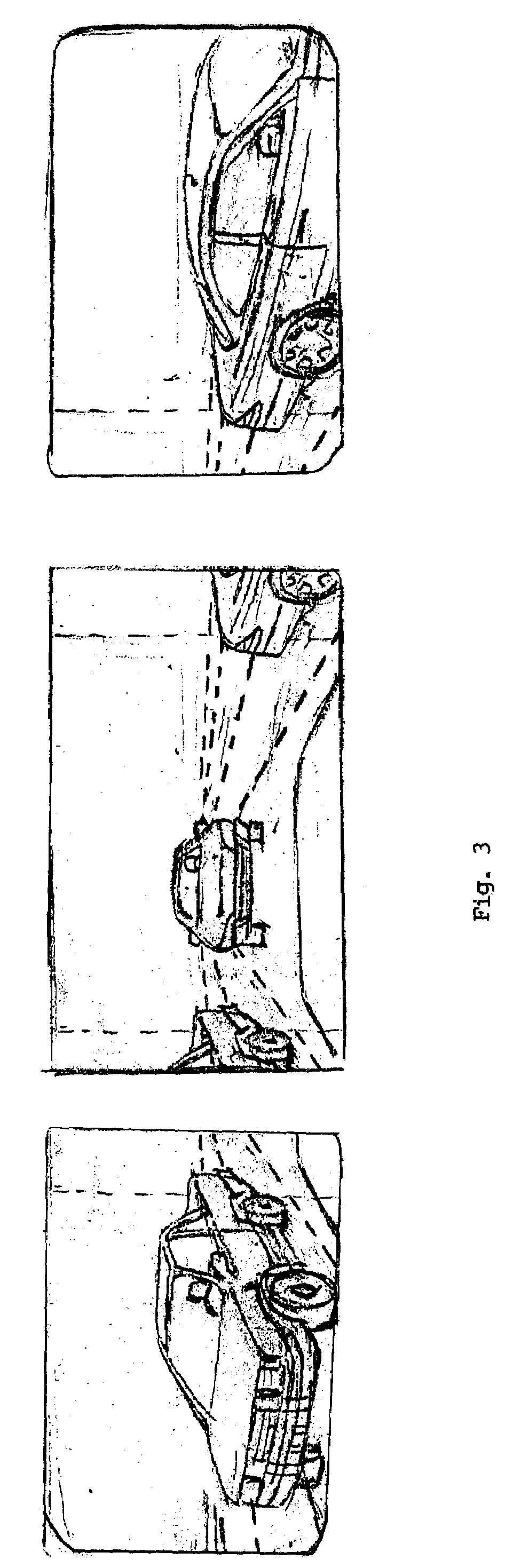
[0019]FIG. 3 shows 3 images taken from the 3 cameras, one from left camera, one from center camera, and one from right camera. Some portion of a vehicle will appear concurrently in two cameras. For example, to the left of the center image, there is a portion of a car that corresp...


PUM


Abstract

A wide-angled display system for automobiles incorporates the use of multiple cameras whose captured images are processed to produce an integrated view, as if viewed directly by human eyes. This integrated view avoids the blind spots inherent in the 3 rear view mirrors currently used. A pseudo-car image (PCI) program logic is described and claimed to transform images of large moving object into smaller objects taking up same length / volume, at the time the large object is approaching from behind, to correct driver misjudgment problem.

Description

BACKGROUND OF INVENTION[0001]The present invention relates generally to design and construction of a wide-angled image display system for use on automobiles.[0002]Present invention solves at least two industry problems: the blind spots that a car driver cannot see and the incorrect evaluation of speed of other larger vehicles.[0003]The use of multiple cameras for capturing separate images, which are views from the sides and back of driver's vehicle, and then feed into an image distribution system to generate an integrated wide-angled eliminates the blind spots.[0004]A computer control unit, employing a program logic described herein, transforms large (seemingly slow-moving) object to several regular-sized automobile images, and thus avoid driver's illusion that a large vehicle is moving slowly, when in fact the large vehicle is moving or approaching very fast.SUMMARY OF INVENTION[0005]Visual illusions, especially in the case of large moving objects, often play tricks to human senses...

Claims


Application Information

Patent Timeline
Patent Type & Authority Patents(United States)
IPC IPC(8): H04N7/18B60R1/00
CPCB60R1/00H04N7/181B60R2300/101B60R2300/105B60R2300/303B60R2300/802B60R2300/8046B60R2300/8066
Inventor XIE, YILING
Owner XIE YILING
Why Eureka
Try Eureka