Gearbox drive unit with an inclined stop surface

a gearbox drive and stop surface technology, applied in the direction of gearing, sliding contact bearings, hoisting equipment, etc., can solve the problem of not being able to allow shaft longitudinal play, and achieve the effect of reliability eliminating the longitudinal play of the sha

Inactive Publication Date: 2008-12-23
ROBERT BOSCH GMBH
View PDF14 Cites 7 Cited by
  • Summary
  • Abstract
  • Description
  • Claims
  • Application Information

AI Technical Summary

Benefits of technology

[0003]The gear drive unit in accordance with the invention has the advantage that an axial force generating device is arranged in such a way that its coefficient of friction prevents a component that equalizes the axial play from receding radially. To do this, the geometry, the surfaces and the materials for the axial force generating device are selected in such a way that the coefficient of friction between a stopping face inclined by an angle of inclination against the perpendicular of the shaft and the surface of the component is greater than the tangent of the angle of inclination. In doing so, the component is displaced radially to the shaft as soon as the shaft has longitudinal play. Pushing back the component is prevented, however, by the frictional condition. As a result, an elastic element, which is used to displace the component, does not have to absorb any high restoring forces, which are initiated via the shaft on the component. Therefore, the elasticity of the elastic element is retained over its entire service life, thereby reliably eliminating the longitudinal play of the shaft over the entire service life.
[0004]In addition, the shaft longitudinal play is hereby eliminated without this longitudinal play having to be measured beforehand during the assembly of the device in order to equalize it, e.g., by means of selectively mounted equalizing plates. As a result, the number of stations on the assembly line is reduced and the assembly device is simplified. The axial force generating device can be manufactured using modular principles so that it is compatible with many different drive units.
[0005]Advantageous developments of the device are possible. Thus, the coefficient of friction between the surface of the component and the inclined stopping face is increased in an especially favorable way by forming a profile on one of the two friction surfaces. If, for example, a saw-tooth-like profile is formed on at least one of the surfaces, the component can be moved radially towards the shaft with less force, but can only be moved back radially again with a considerably higher expenditure of force. As a result, this type of structured surface leads to the elastic element for displacing the component not being excessively stressed. Therefore, the elastic element can be displaced back radially over the entire service life of the device in order to eliminate the axial play that is occurring. Because of forming such a profile on the friction surface between the component and the stopping face, the angle of inclination of the stopping face can be selected to be greater, thereby making greater travel available to equalize the shaft longitudinal play. In a preferred embodiment, one of the two stopping faces or the component can feature a stair-step-like surface, in which the “stepping surfaces” are aligned to be approximately perpendicular to the longitudinal axis of the shaft. As a result, a restoring force of the component radially away from the shaft is practically completely prevented with the effect of a axial force from the shaft. This produces a situation where no shaft longitudinal play is permitted even in the case of extreme loads on the shaft.

Problems solved by technology

This produces a situation where no shaft longitudinal play is permitted even in the case of extreme loads on the shaft.

Method used


Image

  • Gearbox drive unit with an inclined stop surface
  • Gearbox drive unit with an inclined stop surface
  • Gearbox drive unit with an inclined stop surface

Examples


Embodiment Construction

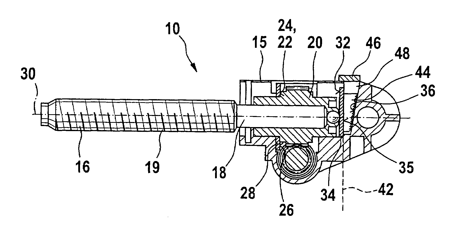
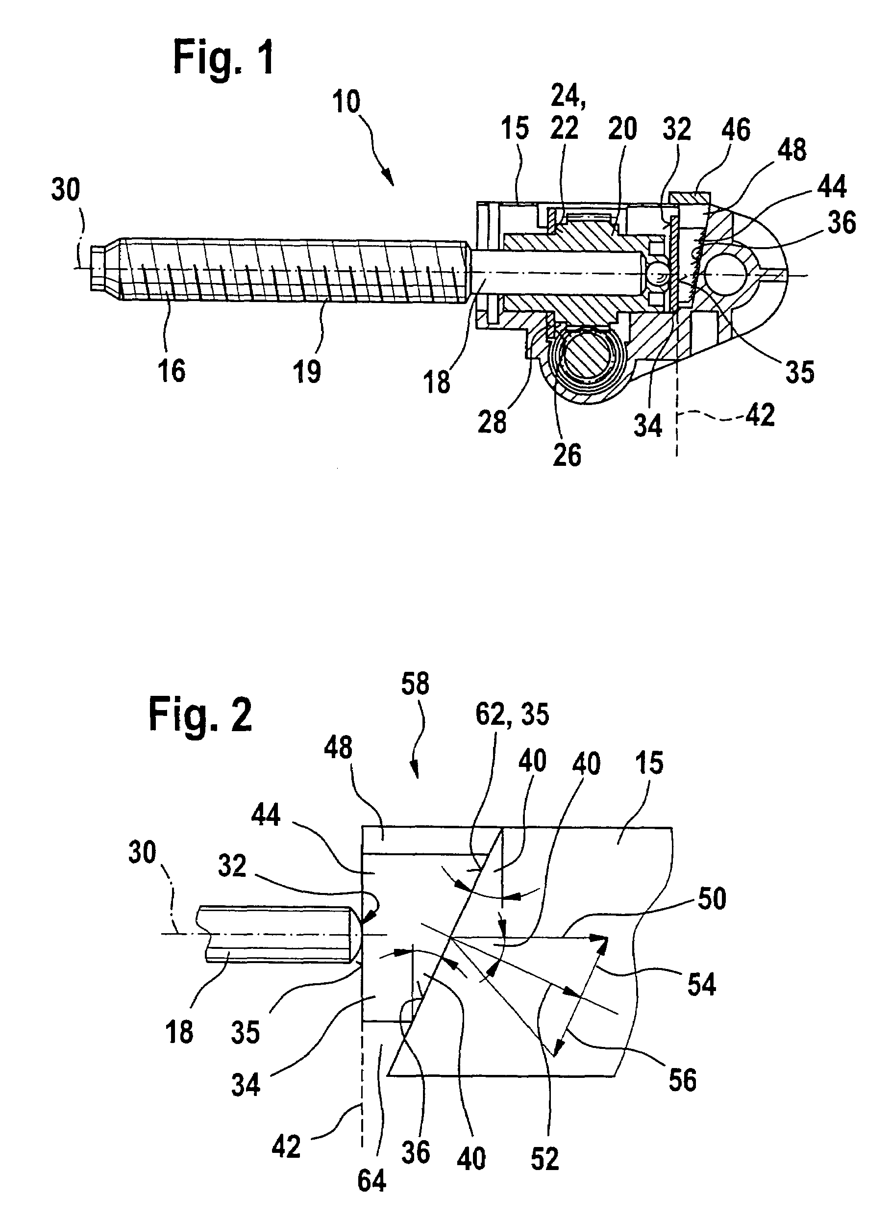
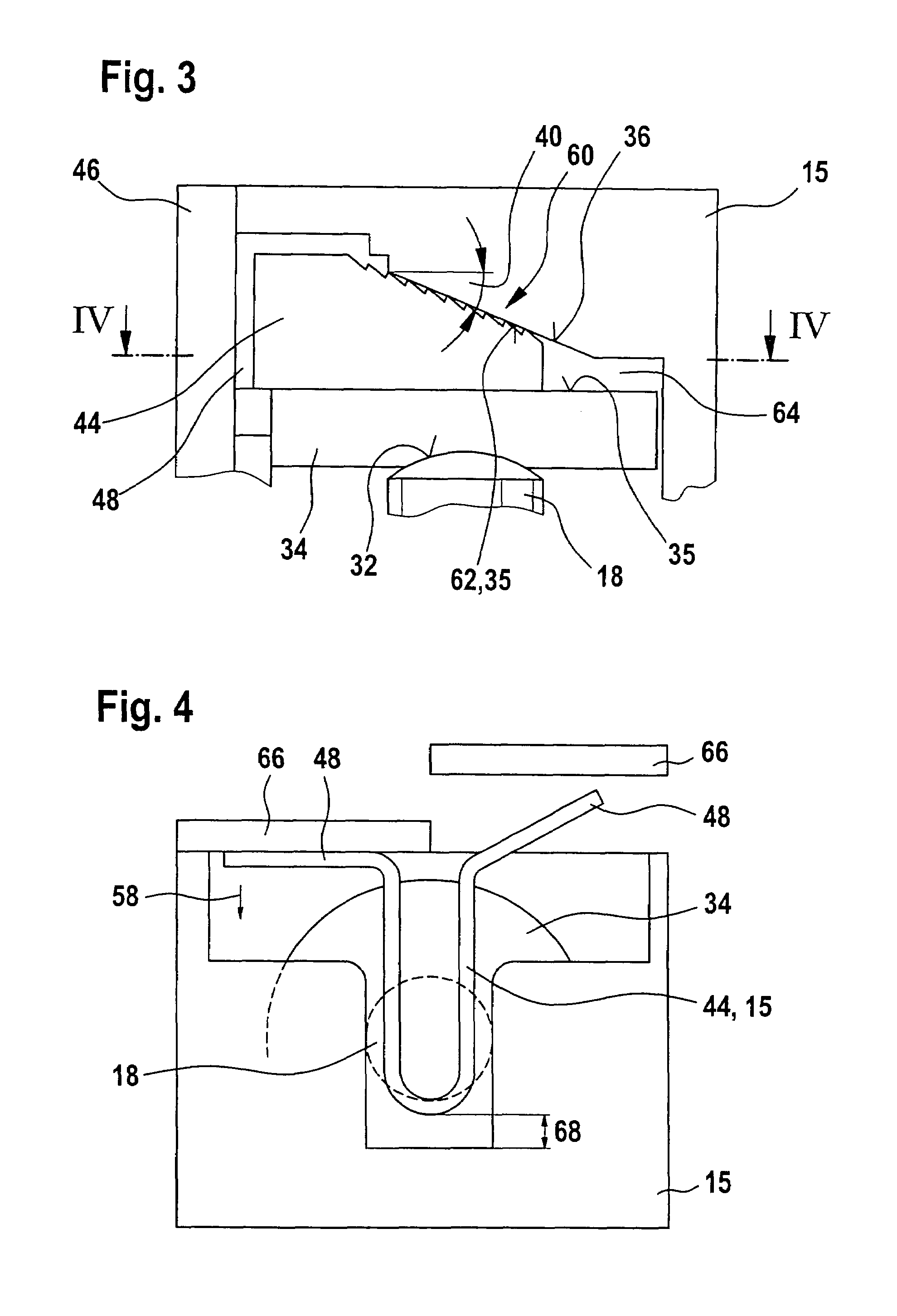
[0036]The exemplary embodiment depicted in FIG. 1 shows a section of a gear drive unit 10 in accordance with the invention in which an electric motor 12 (not shown in greater detail) drives via a worm gear 14 a shaft 18 embodied as a spindle 16, which projects out of the gear housing 15 of the worm gear 14. A worm wheel 20 featuring a collar 22 is formed on the shaft 18. This collar 22 forms a first stopping face 24, which is supported on a counter stopping face 26 of a stopping plate 28, which is adjacent to the gear housing 15. The shaft 18 that is positioned along a longitudinal axis 30 is supported with a fore part 32 on another stopping element 34 on the front side, which features a stopping face 35 on the side facing away from the fore part 32. Embodied on the gear housing 15 is another stopping face 36, which is inclined by an angle of inclination 40 against a plane 42 perpendicular to the longitudinal axis 30. Arranged between the diagonal stopping face 36 and the stopping f...


PUM


Abstract

The invention relates to a gear drive unit (10), in particular to adjust moveable parts in a motor vehicle, with a gear housing (15) and a shaft (18) positioned therein along a longitudinal axis (30), which shaft is supported on the housing (15) via an axial stopping face (35) on a counter stopping face (36), wherein at least one of the stopping faces (35, 36) is inclined perpendicular to the longitudinal axis (30) against a plane (42) by an angle of inclination (40) in order to generate an axial force, and a component (44), which cooperates with at least one of the stopping faces (35, 36), is arranged in a displaceable manner perpendicular to the longitudinal axis (30). In doing so, the coefficient of friction between the at least one stopping face (35, 36) and the component (44) is greater than the tangent of the angle of inclination (40).

Description

BACKGROUND OF THE INVENTION[0001]The invention starts with a gear drive unite, in particular for adjusting moveable parts in a motor vehicle.[0002]A drive device for a windshield wiper system of a motor vehicle, which features a housing and an armature shaft positioned rotatably therein that has a worm, became known with DE 198 545 35 A1. Using an axial force generating device, a wedge slider is hereby displaced radially to the armature shaft in order to equalize the axial play of the armature shaft. The displacement force of the wedge slider is applied via a pre-stressed spring element, which presses the wedge slider radially against a limit stop of the armature shaft, thereby displacing the shaft axially until the axial play is equalized. On the other hand, with a great load to the armature shaft via a driven gear, an axial force occurs, which presses the armature shaft against the wedge slider and in doing so the wedge slider is pressed back radially away from the armature shaft ...

Claims


Application Information

Patent Timeline
Patent Type & Authority Patents(United States)
IPC IPC(8): F16H55/18F16H1/16F16C17/08F16H57/021F16H57/022H02K7/08
CPCF16C17/08F16H1/16F16H57/021H02K7/081F16H2057/0221Y10T74/18728Y10T74/19623Y10T74/19828F16H2057/127F16C2361/61
Inventor OBERLE, HANS-JUERGENLIENIG, ANDREASHUESGES, MARIOLOUVEL, FABIAN
Owner ROBERT BOSCH GMBH
Why Eureka
Try Eureka