Slurry tolerant pilot operated relief valve

a relief valve and pilot operation technology, applied in fluid pressure control, instruments, borehole/well accessories, etc., can solve problems such as device loss, potential for device to lose functionality, and flow used to communicate pressure laden with particulates

Active Publication Date: 2008-12-23
EXXONMOBIL UPSTREAM RES CO
View PDF27 Cites 16 Cited by
  • Summary
  • Abstract
  • Description
  • Claims
  • Application Information

AI Technical Summary

Problems solved by technology

Operational challenges arise when the flow used to communicate pressure is laden with particulates.
These particulates introduce the potential for a device to lose functionality as a result of solids becoming lodged in a device's moving parts, as well as damage resulting from the cutting capacity of high velocity, particle-laden fluid streams passing over a device's sealing components.
The use of rigid seal materials such as metal or thermoplastics enhance the durability of a device, but compromise the sealability of the device.
For example, a steel ball could never seal a circular steel aperture if a sand grain was wedged between the steel ball and the edge of the aperture (or if the edge of the aperture was slightly nicked).
While the rubber ball is a superior sealing material, it is also highly susceptible to damage from the cutting action of high velocity fluid streams.
ty. Valve designs that involve an isolated, or sealed, static pressure exhibit limited functionality in a downhole environm
epth. This change in static pressure results in a change in valve performance as a function of d
In addition, when valves are deployed downhole they are not readily accessible for servicing; thus significant expense is typically incurred if valve failures occur during an intervention program.
The valves tend to have rigid seal materials and are designed in a fashion that are susceptible to compromised functionality due to particulate bridging between the rigid seal materials.
Current technology does not provide a suitable physical design, or design concept for the problem.

Method used


Image

  • Slurry tolerant pilot operated relief valve
  • Slurry tolerant pilot operated relief valve

Examples


examples

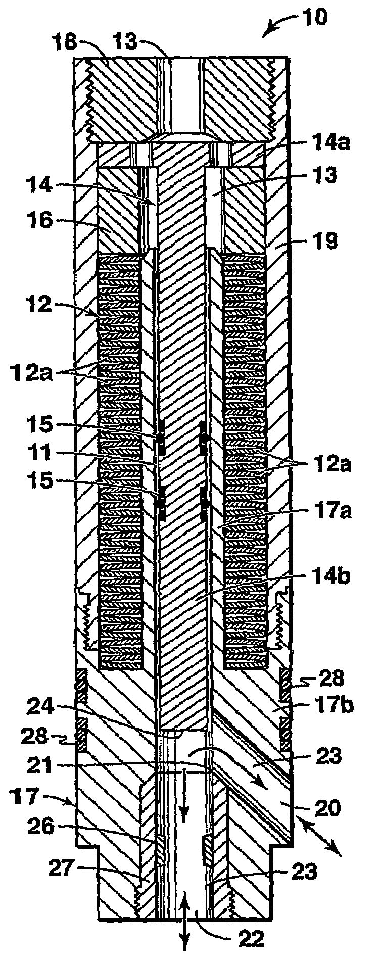
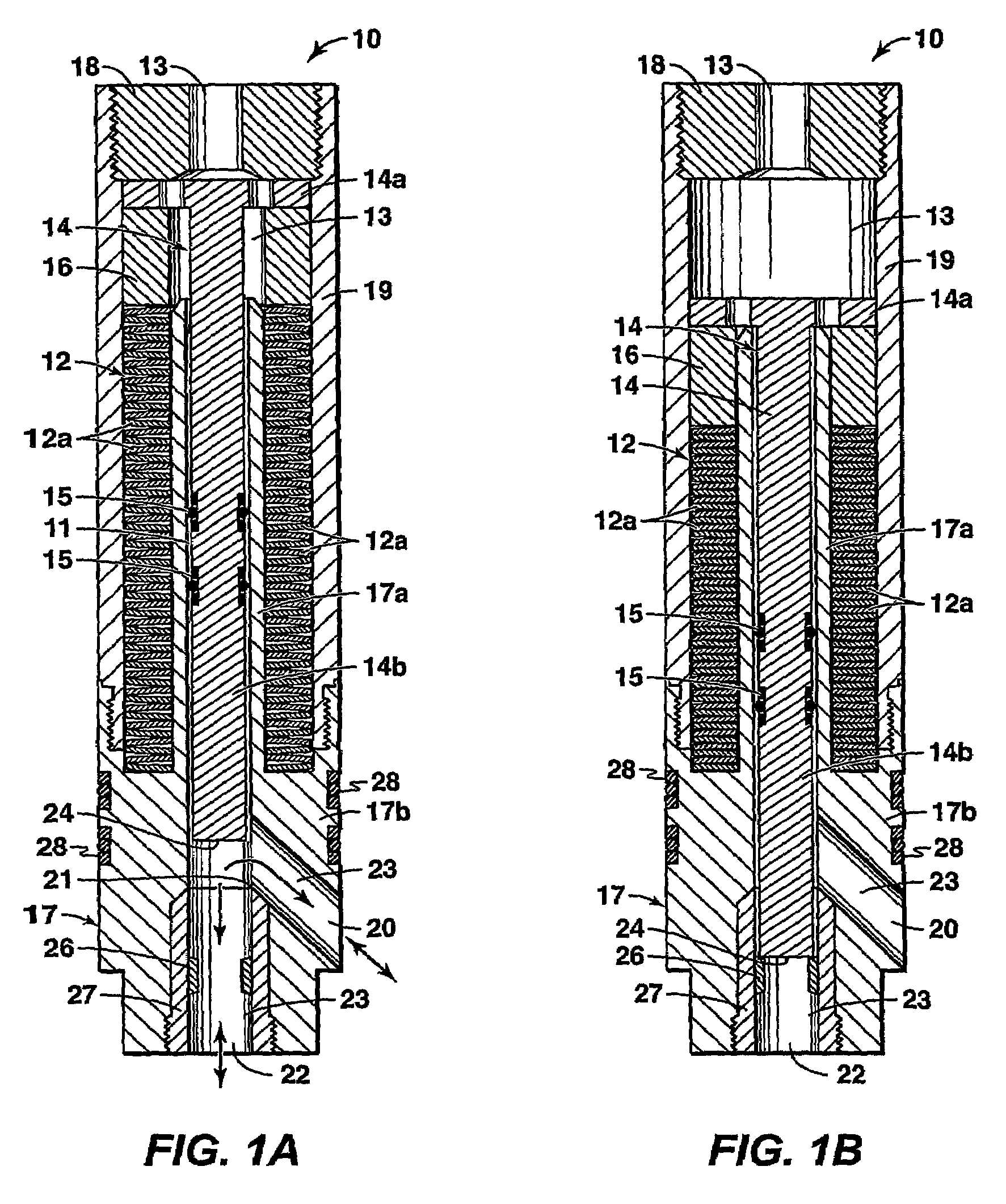
[0029]The following discussion provides a paper example that is based on deployment of a pilot operated relief valve (PORV) according to this invention in a fracture stimulation application. For this example a coiled tubing deployed bottom-hole-assembly (BHA) is assumed and this BHA is comprised of an inflatable packer and a circuit of cartridge valves that perform tasks as a function of applied pressure. It is also assumed that packer inflation occurs via applied coiled tubing pressure, and the PORV port for actuation fluid (fluid 13 in the drawings) is in communication with the coiled tubing. Additionally, it is assumed that an independent flow passage exists through the center of the packer with one passage in the PORV (passage 20 in the drawings) in communication with the annular fluid uphole of the packer and another passage (passage 22 in the drawings) being in communication with the fluid downhole of the packer. It is also assumed that the fracture stimulation is pumped betwe...


PUM


Abstract

Cartridge-style fluid control devices are provided that are static pressure independent and capable of repeatable, reliable, particulate insensitive performance in service conditions typical of downhole intervention environments.

Description

[0001]This application is the National Stage of International Application No. PCT / US04 / 029831, filed 14 Sep. 2004, which claims the benefit of U.S. Provisional Patent Application No. 60 / 503,042, filed 15 Sep. 2003.FIELD OF THE INVENTION[0002]This invention pertains to fluid control devices for metering, maintaining, and isolating fluid pressure and flow between two or more sources.BACKGROUND OF THE INVENTION[0003]Fluid control is routinely practiced within a wide variety of industries. Control is typically achieved using devices that are specifically designed to perform a unique control operation. Examples of such control devices are pressure relief valves, pressure regulators, back-pressure regulators, velocity fuses, mass flow controllers, pilot operated valves, check valves, and shuttle valves.[0004]Pressure is typically communicated from one source to another via the flow of gas or liquid. Operational challenges arise when the flow used to communicate pressure is laden with part...

Claims


Application Information

Patent Timeline
Patent Type & Authority Patents(United States)
IPC IPC(8): F16K31/00F16K31/122F16K31/143F16K31/163F16K31/363F16K31/383G05D7/01G05D16/10
CPCE21B21/10F16K17/082F16K31/1221F16K31/363G05D16/18G05D16/187
Inventor LONNES, STEVEN B.
Owner EXXONMOBIL UPSTREAM RES CO
Why Eureka
Try Eureka