
Arresting systems and methods

a technology of arresting systems and vehicles, applied in the field of systems and methods, can solve problems such as reducing the likelihood of injury to occupants of arrested vehicles, and achieve the effect of reducing the likelihood of injury to occupants

Active Publication Date: 2008-12-23
ENGINEERED ARRESTING SYST CORP
View PDF25 Cites 16 Cited by
  • Summary
  • Abstract
  • Description
  • Claims
  • Application Information

AI Technical Summary

Benefits of technology

"The present invention provides systems and methods for arresting the movement of objects such as vehicles. The systems are bi-directional and can be quickly reset for reuse. They use a net as a barrier to travel and may also include brake-in-spool assemblies and arresting tapes. The systems can be used on roadways, runways, or other surfaces. The invention also includes energy absorbers in the form of brake assemblies positioned at opposite sides of a surface to slow down moving objects. The systems can be used regardless of the direction of travel of the objects. The invention also provides for the use of friction brakes in connection with the nets. Overall, the invention provides effective and safe systems for arresting the movement of objects."

Problems solved by technology

Such systems additionally may use some or substantially all of available stopping space when deployed, potentially reducing likelihood of injury to occupants of arrested vehicles.

Method used


Image

  • Arresting systems and methods
  • Arresting systems and methods
  • Arresting systems and methods

Examples


Embodiment Construction

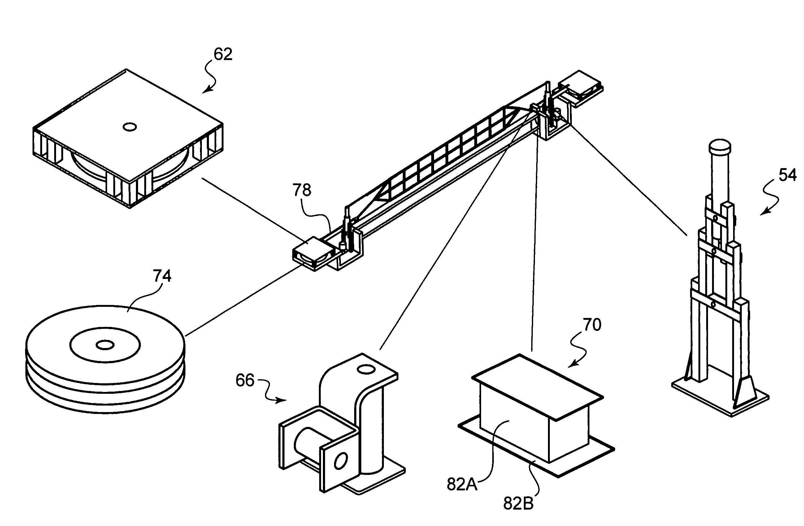
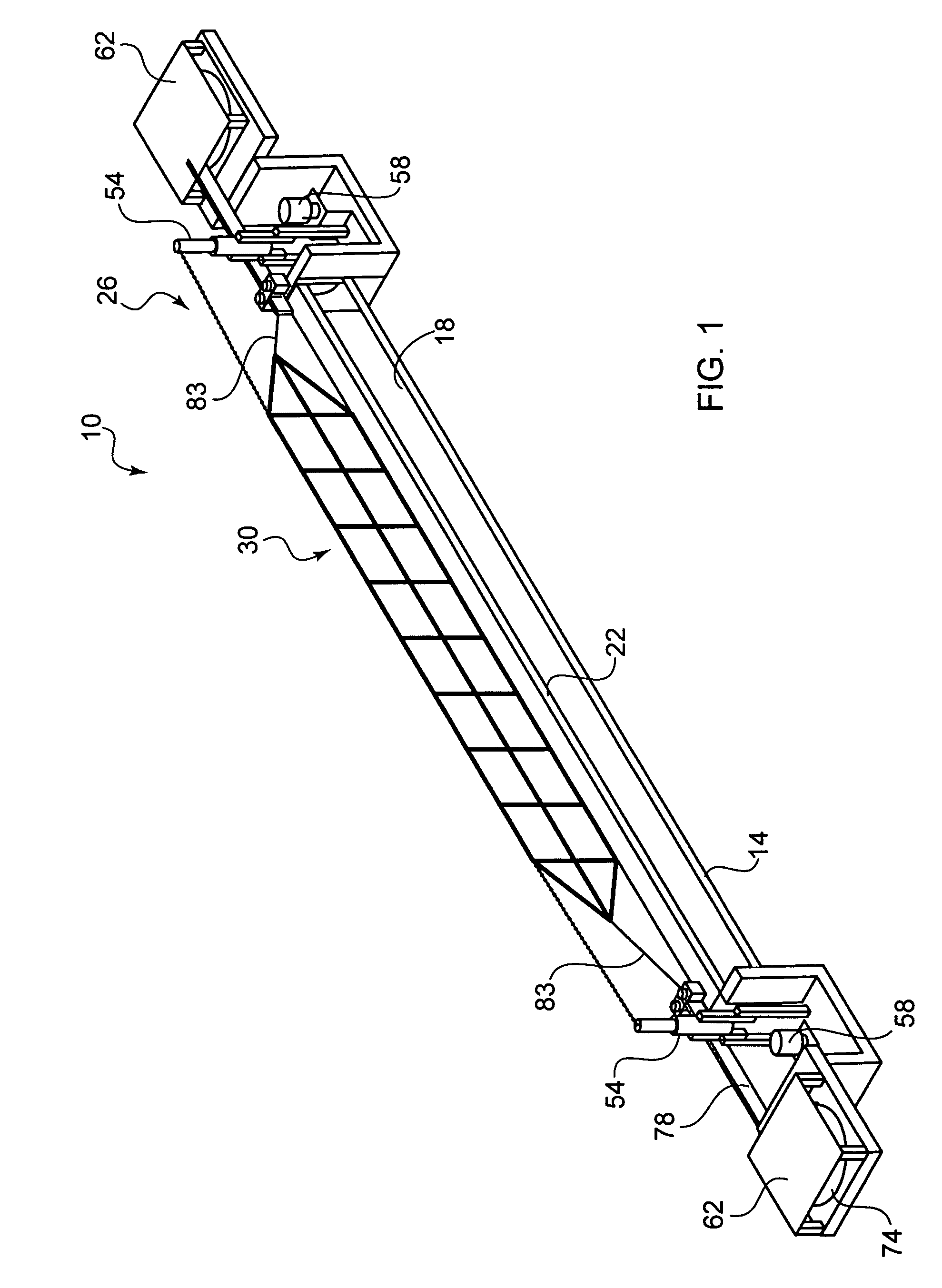
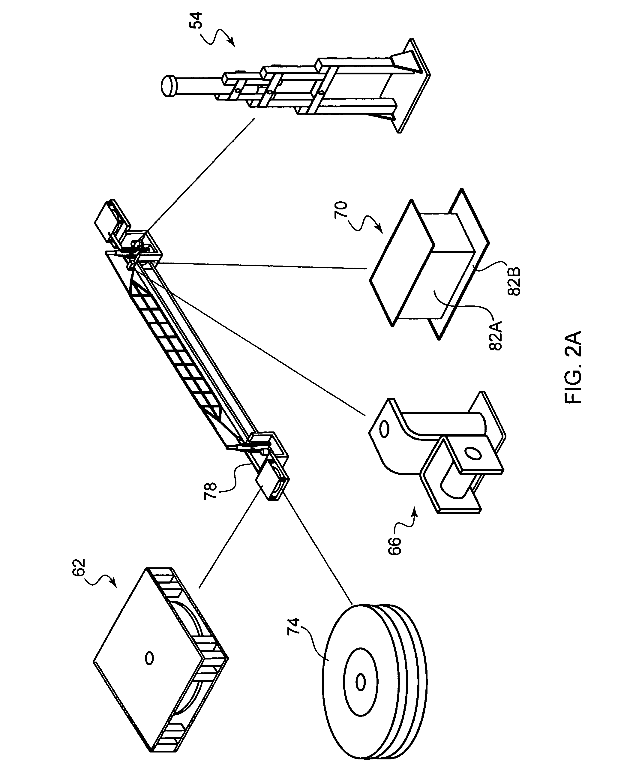
[0019]Depicted in FIGS. 1 and 2A-B is exemplary system 10 of the present invention. System 10 is denoted “in-ground” because many of its components are below grade (at least prior to deployment). Those skilled in the relevant field will recognize that not all components of system 10 need necessarily be below grade prior to deployment, so system 10 may be constructed differently than as shown in FIGS. 1 and 2A-C.

[0020]Nevertheless, system 10 preferably includes module 14, which beneficially may be a pre-cast block or beam of concrete. Module 14 typically will be elongated, with a length greater than the width of the roadway, runway, or other travel surface with which it is deployed. When positioned across such travel surface, therefore, module 14 will span its width.

[0021]Module 14 additionally is designed to be embedded in the travel surface with its upper surface 18 flush therewith. Upper surface 18 itself thus may form part of the travel surface. Accordingly, module 10 should be o...


PUM


Abstract

Systems and methods for arresting vehicles or other moving objects are detailed. The systems may be bi-directional, so as to arrest vehicles on either side of a barrier. They additionally may be reset for reuse relatively rapidly following deployment.

Description

FIELD OF THE INVENTION[0001]This invention relates to systems and methods for impeding movement of moving objects and more particularly, although not necessarily exclusively, to bidirectional, reusable systems and methods for arresting travel of ground-based vehicles.BACKGROUND OF THE INVENTION[0002]U.S. Pat. No. 6,843,613 to Gelfand, et al. discloses an energy absorbing system forming part of an automobile barrier for placement preferably at a railroad crossing. The system includes a net stored in a pit spanning a roadway and parallel to railroad tracks. The net may be raised as an automobile approaches along the roadway in a particular travel direction; should the automobile not stop timely it will collide with the net, causing the automobile to cease travel prior to reaching the tracks.[0003]The system of the Gelfand patent also contemplates placing a second automobile barrier opposite the railroad tracks from the first barrier. Such a two-barrier system is depicted especially in...

Claims


Application Information

Patent Timeline
Patent Type & Authority Patents(United States)
IPC IPC(8): E01F13/04E01F13/00
CPCE01F13/044E01F13/048E01F13/12E01F13/123B61L29/04
Inventor ORNER, JR., RICHARD L.LURQUIN, JR., JOSEPH W.QUINN, THOMAS L.ROBERTSON, DONALDALLEN, MARK W.
Owner ENGINEERED ARRESTING SYST CORP
Learn More