Chuck for receiving tools operated by rotating around the axis thereof

Inactive Publication Date: 2008-12-30
WERA WERK HERMANN WERNER GMBH & CO KG
View PDF27 Cites 62 Cited by
  • Summary
  • Abstract
  • Description
  • Claims
  • Application Information

AI Technical Summary

Benefits of technology

[0004]Therefore, the invention is based on the object of further developing a chuck of the generic

Problems solved by technology

In particular short and thin bits can only be removed from t

Method used


Image

  • Chuck for receiving tools operated by rotating around the axis thereof
  • Chuck for receiving tools operated by rotating around the axis thereof
  • Chuck for receiving tools operated by rotating around the axis thereof

Examples


Example

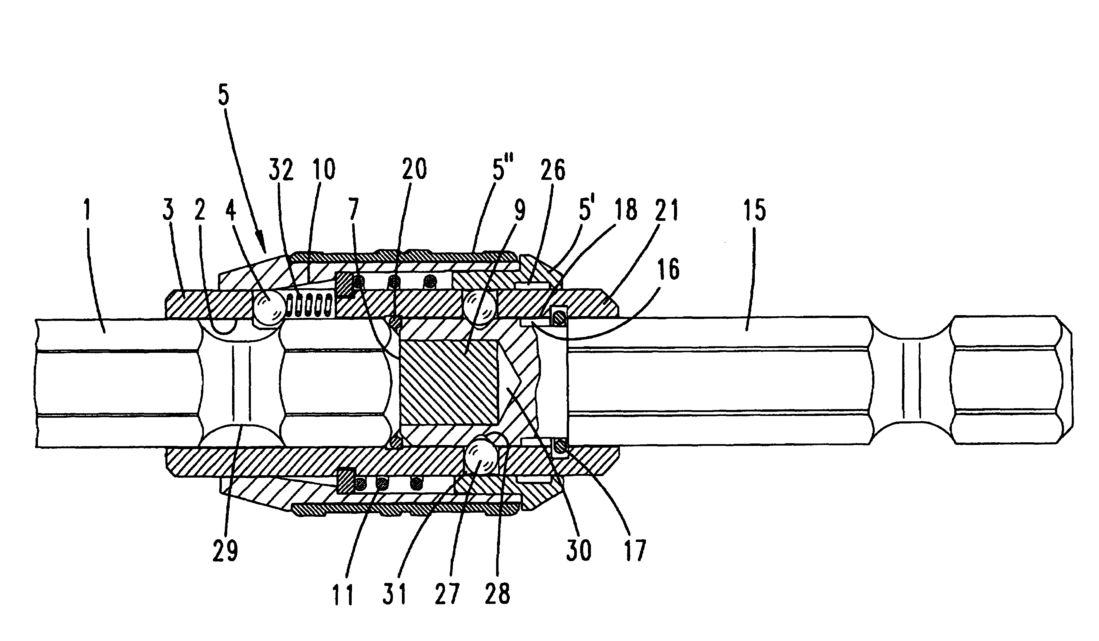
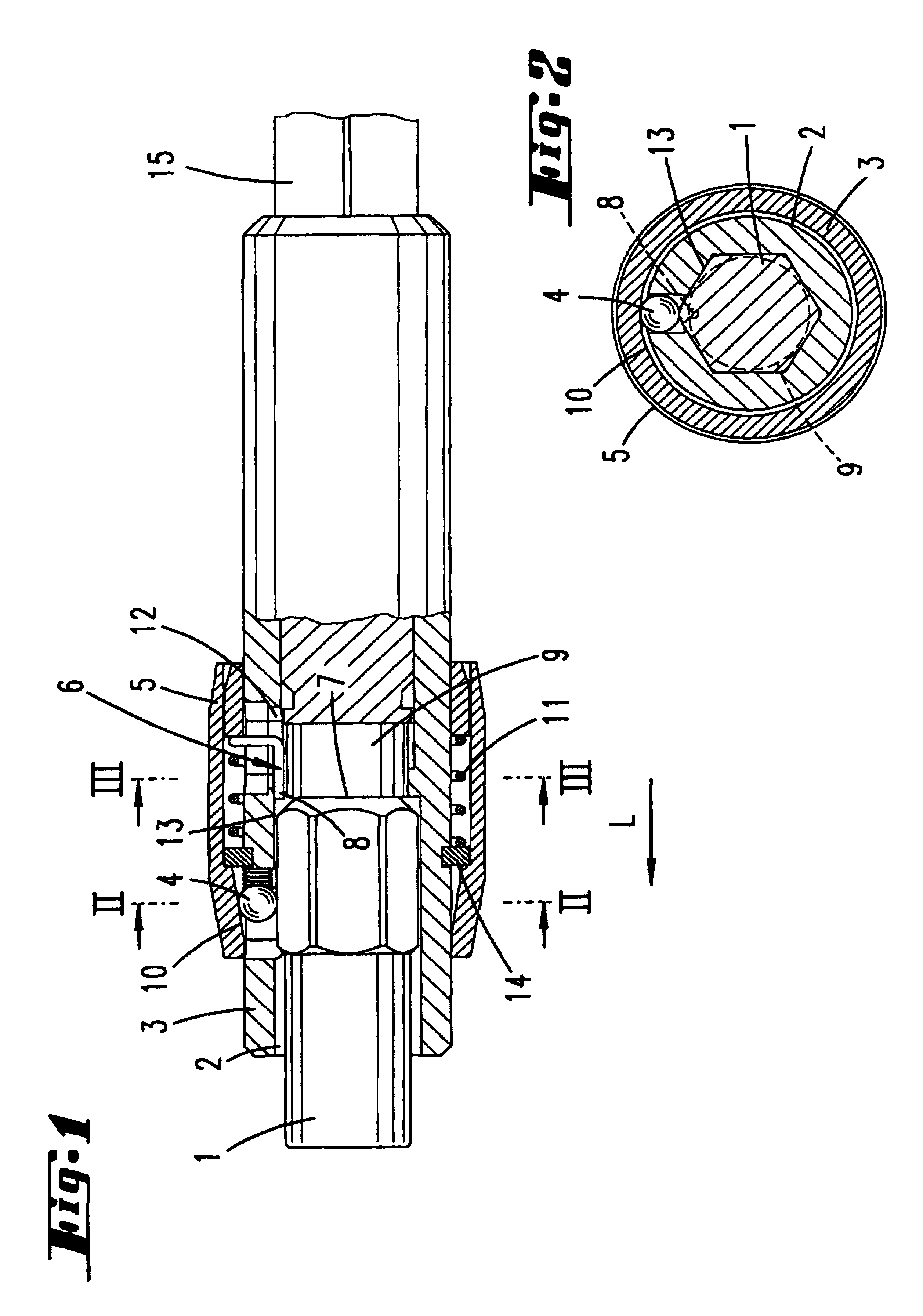
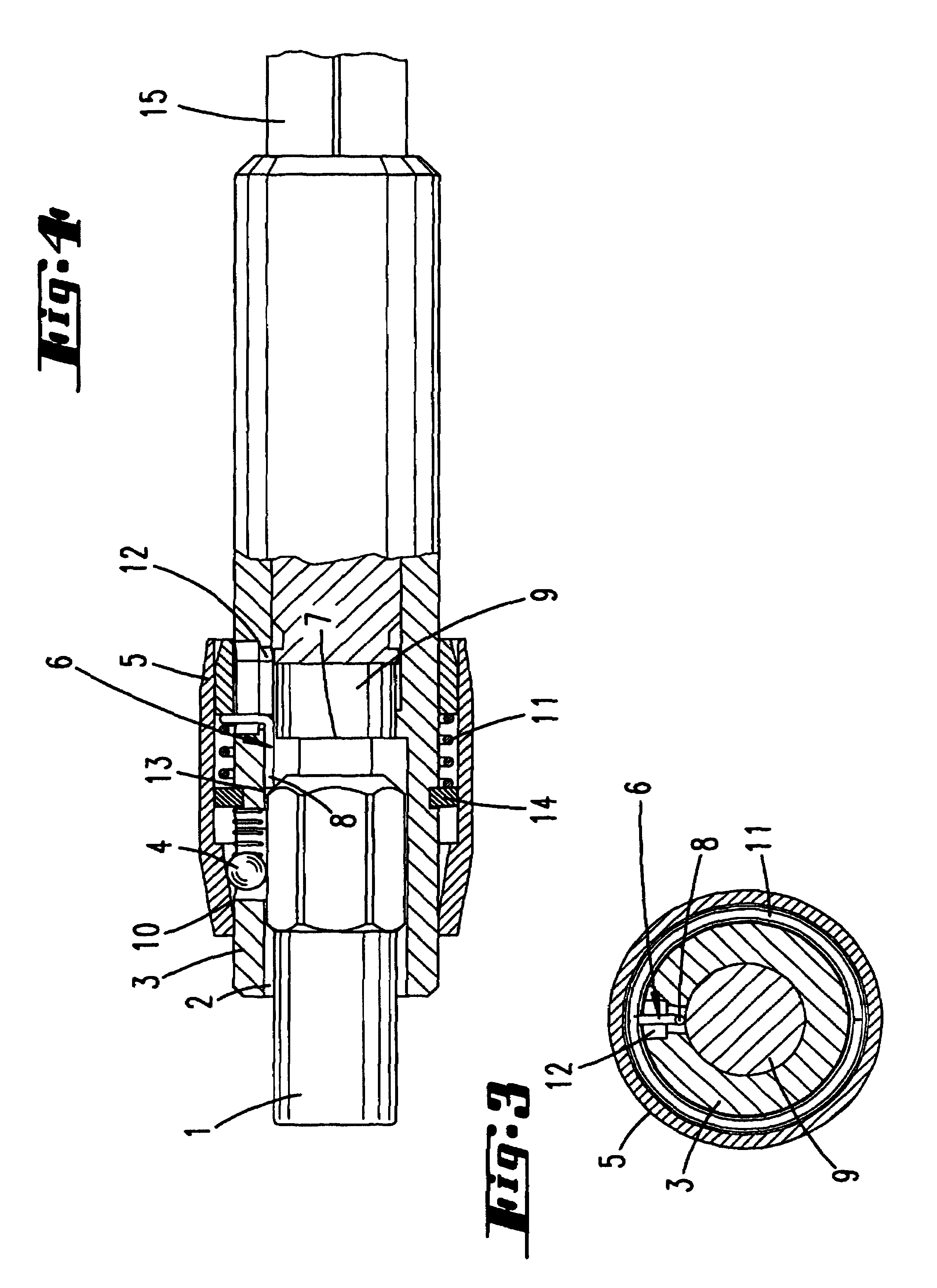
[0025]The chuck has an insertion portion 3 and a hexagonal clamp-in portion 15. This insertion portion 3 may consist of metal and at one end has a receiving cavity 2 for a screwdriver insert 1, in the form of a bit. At the other end, a clamp-in shank 15, the hexagon portion of which can be fitted into a chuck of an electric screwdriver, projects out of the insertion portion. With regard to the configuration of this clamp-in shank, reference is made to the prior art cited in the introduction. The clamp-in portion 15 can be pressed into a cavity in the insertion portion 3.

[0026]As can be seen from FIG. 2, the receiving cavity 2 has a hexagonal cross section. A window is located in the region of an edge of the receiving cavity 2. In this aperture formed by the window there is located a ball 4 which forms the holding element and the diameter of which is greater than the wall thickness, so that the ball 4 can extend into the receiving cavity 2, in order there to hold the bit by being sup...


PUM


Abstract

A chuck for receiving tools (1) that are operated by rotating around the axis thereof, particularly screwdriver bits, and having an insertion section (3) which is provided with a receiving cavity (2) having a non-circular cross-sectional area (3). The tool can be locked in the cavity (2) by a holding element (4) which is assigned to the cavity wall in order to prevent the tool from being withdrawn from the cavity (2). The holding element (4) can be deactivated by displacing an actuating member in a form of an actuating sleeve (5). The tool (1) rests backwards against the cavity (2). The tool (1) can be displaced from the resting position in the direction of the opening of the cavity (2) by actuating the actuating sleeve (5). In order to facilitate removal of the bit, the chuck also comprises components (15, 16, 17) for releasing the face (1) of the bit, and a magnet (9) which retains the bit in the cavity from the resting position.

Description

FIELD AND BACKGROUND OF THE INVENTION[0001]The invention relates to a chuck for receiving tools which can be used by rotation about their axis, in particular screwdriver inserts, having an insertion portion having a receiving cavity which has a cross-sectional area that is not round, in which receiving cavity the tool can be secured by means of a holding element associated with the wall of the cavity against being pulled out of the receiving cavity, which holding element can be deactivated by a sliding movement of an actuating member, in particular in the form of an actuating sleeve, the tool being supported at the rear in the receiving cavity.[0002]Chucks of this type are described by DE 29 34 428 and DE 199 32 369. In those documents, the polygonal portion of a bit is fitted into a polygonal bore in an insertion portion. A holding element which is formed by a ball acts on the outer surface of the bit, in particular on its edge or edge cutout. The ball is pressed radially inward on...

Claims


Application Information

Patent Timeline
IPC IPC(8): B23B31/22B25B23/00B25B21/00
CPCB25B23/0035Y10S279/905Y10T279/3406Y10T279/17752B25B23/12
Inventor STRAUCH, MARTINABEL, MICHAELMULLER, ANDRE
Owner WERA WERK HERMANN WERNER GMBH & CO KG
Why Eureka
Try Eureka