Quick connect coupling with disconnect lock

a technology of disconnect lock and coupling, which is applied in the direction of couplings, pipe elements, engine seals, etc., can solve the problems of couplings and achieve the effect of reducing the chance of hose kinking

Active Publication Date: 2008-12-30
THE GATES CORP
View PDF34 Cites 29 Cited by
  • Summary
  • Abstract
  • Description
  • Claims
  • Application Information

AI Technical Summary

Benefits of technology

[0010]It is thus one aspect of the present invention to provide a coupling that generally includes a male portion and a female portion which are operably and selectively interconnected. The female portion generally interconnects to a fixed port, or adapter for engagement with a port, such as a commonly known hexhead fluid boss. The male portion interconnects generally to a flexible fluid line, and selectively interconnects with the female portion. One embodiment also includes a locking device such that the coupling cannot be disconnected until the locking device is disengaged. The present invention may generally be interconnected and disconnected without the need of tools, such as wrenches. In addition, the coupling decreases the chance of hose kinking because the coupled portions may generally be rotated with respect to each other while remaining connected.
[0011]One embodiment of the present invention includes a locking mechanism that resides around the male portion of the coupling. More specifically, the locking mechanism is generally a cylinder that includes two ends, wherein one end has at least one cut-out or circumferential groove integrated therein. The cut-out allows that end of the cylinder to resiliently deflect when a radial force is applied thereto to create a conical shape. To disengage the coupling, the locking device is radially deflected into a release groove integrated into the male portion of the coupling. The locking mechanism also includes a thickened wall adjacent to the edge that employs the cut-out(s). The thickened edge preferably engages a locking groove integrated into the female portion of the coupling when the lock is at its nominal position. Upon deflection of the locking device, the thicker portion is unseated from the locking groove of the female portion, thus facilitating removal of the two portions. The locking device is generally constructed of a resilient material, such as steel, aluminum, plastic, Teflon, etc. In addition, the locking device may be of various shapes to facilitate locking of the two portions, and may include a sloped surface wherein contact with the outside surface of the female portion during coupling will cause radial deflection of at least a portion of the locking device. More specifically, an angled surface may be included in the thicker portion of the locking device such that axial loads on the locking device generated by coupling are redirected radially, thus facilitating deflection of an end of the locking device to its smaller radius configuration.
[0012]It is another aspect of the present invention to provide a locking device as described above that includes a protrusion integrated in the thicker portion that engages a receiving groove in the female portion of the coupling. Upon insertion of the male portion into the female portion, the protrusion of the locking device encounters a lip of the locking groove, wherein further insertion provides an unobstructed path that allows the locking device to return to its nominal undeflected position with the receiving groove of the locking groove adjacent to the protrusion. Once pressure is introduced to the coupling, the male portion and the female portion will tend to separate, thus seating the protrusion inside the receiving groove. The two portions cannot be separated until the system pressure is reduced thereby allowing the male portion to be inserted further into the female portion such that the protrusion can clear the receiving groove when the locking device is deflected by the release mechanism.

Problems solved by technology

In addition, the coupling decreases the chance of hose kinking because the coupled portions may generally be rotated with respect to each other while remaining connected.

Method used


Image

  • Quick connect coupling with disconnect lock
  • Quick connect coupling with disconnect lock
  • Quick connect coupling with disconnect lock

Examples


Embodiment Construction

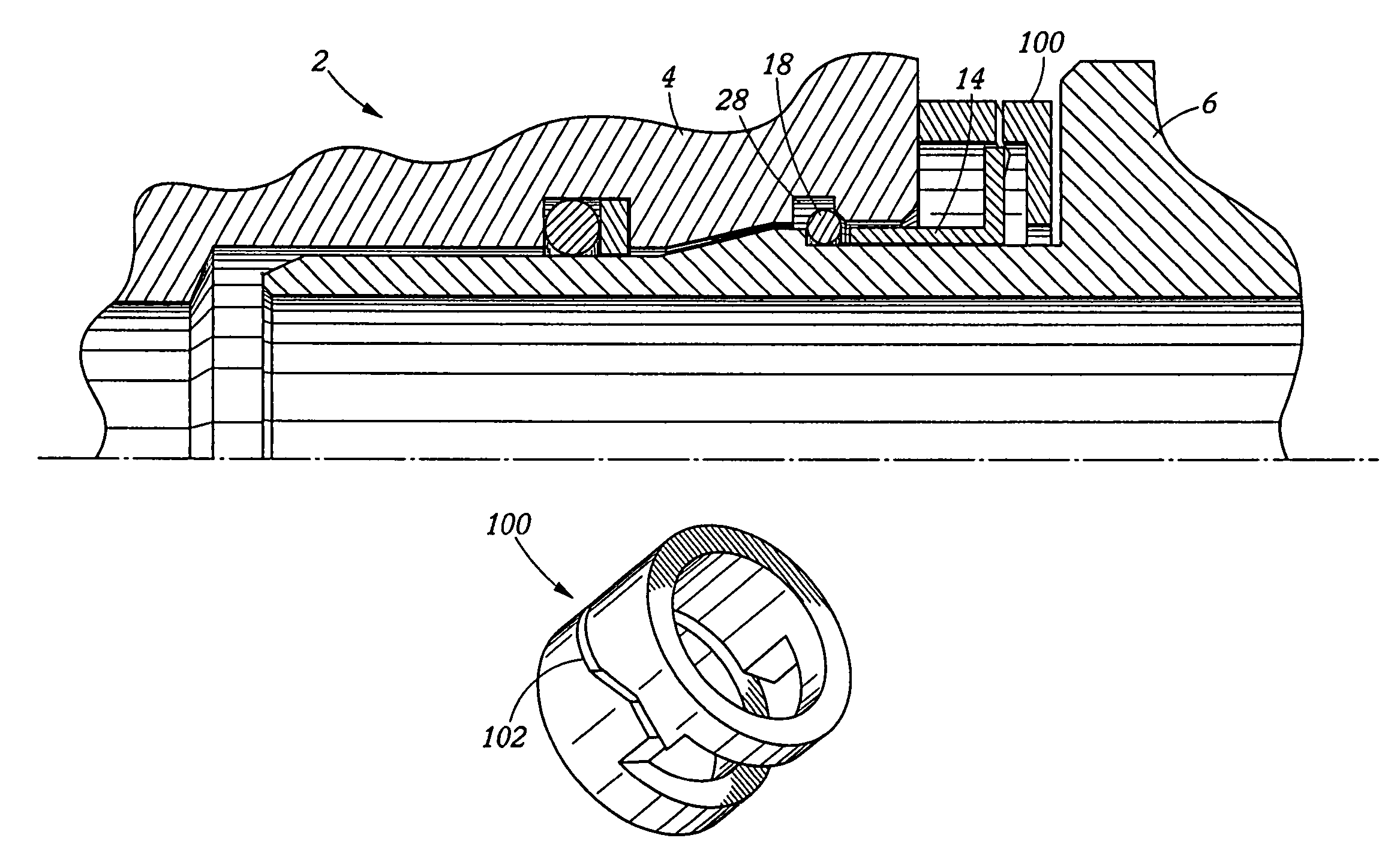
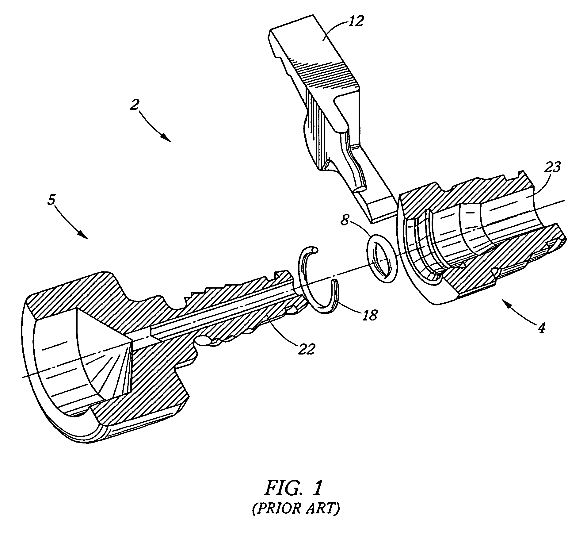
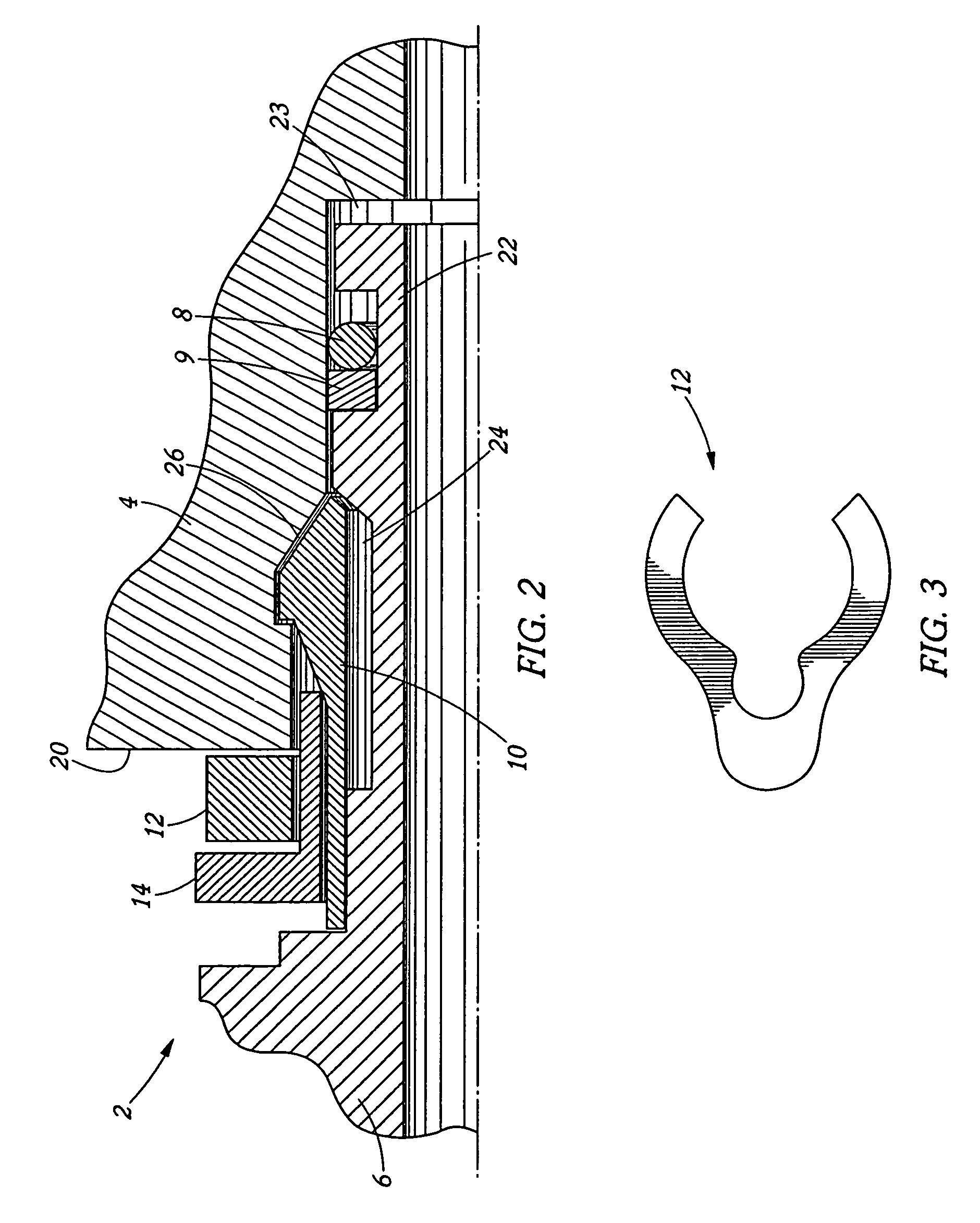
[0088]Referring now to FIG. 1, an example of a prior art quick connect coupling 2 is shown. More specifically, hydraulic and pneumatic quick connect coupling 2 generally includes a female portion 4 that is a cylindrical shaped member with an inner diameter and an outer diameter such that liquids and / or gases may pass freely therethrough. Quick connects also include a male portion 6 for operable engagement with the female portion 4. The male portion 6 generally has at least one groove where at least one seal 8 may be interconnected. The inner diameter of the male portion 6 is generally less than the inner diameter of the female portion 4 of the coupling to allow selective engagement and disengagement. In order to maintain the integrity of the quick connect coupling 2, a space 12 may be used to prevent unwanted deflection of the male portion 6 into the female portion 4. More specifically, once a locking snap ring 18 is deformed, it engages a cavity in the female portion 4, thus preven...


PUM


Abstract

A coupling assembly is provided that generally includes a female coupling selectively interconnected to a male coupling to provide sealing engagement. In one embodiment, the female coupling and the male coupling are secured together by a mechanical locking mechanism that is disengaged with a release mechanism. To prevent inadvertent disengagement, a secondary locking device or spacer is provided which substantially prevents the release mechanism from disengaging the locking mechanism.

Description

[0001]This application claims the benefit of U.S. provisional patent application 60 / 660,971, filed Mar. 11, 2005, which is incorporated by reference in its entirety herein.FIELD OF THE INVENTION[0002]The present invention relates generally to quick connect couplings that can be quickly connected and disconnected. One embodiment of the invention further comprises a removable safety mechanism that prevents the inadvertent disengagement of the quick connect coupling.BACKGROUND OF THE INVENTION[0003]Quick connect hydraulic and pneumatic couplings typically include a male portion in operable engagement with a female portion. The male and female portions may be interconnected to a hydraulic hose, tubing, piping, machinery or open apparatus that utilizes internal pressure. Since hydraulic hoses and interconnecting machinery often utilize high pressure fluids, safety and operational considerations are paramount since an inadvertent disconnection of the coupling may result in serious injury ...

Claims


Application Information

Patent Timeline
Patent Type & Authority Patents(United States)
IPC IPC(8): F16L55/00
CPCF16L37/0847F16L37/088F16L37/0982F16L37/0887
Inventor SWIFT, JONATHAN C.KEAST, GEOFFREY R.ROBINSON, TIMOTHY G.MCGEE, STEPHEN
Owner THE GATES CORP
Why Eureka
Try Eureka