Automatic transmission control device

a transmission control and automatic technology, applied in the direction of gearing control, gearing element, belt/chain/gearing, etc., can solve the problem of further improvement, and achieve the effect of suppressing the discomfort of manipulation feeling, enhancing the drivability, and reducing the load attributed to an excessive engine brake for

Inactive Publication Date: 2008-12-30
HONDA MOTOR CO LTD
View PDF8 Cites 6 Cited by
  • Summary
  • Abstract
  • Description
  • Claims
  • Application Information

AI Technical Summary

Benefits of technology

[0005]It is an object of the present invention to provide an automatic transmission control device which overcomes the above-mentioned drawback of the conventional art and obtains proper shift-down timing by taking the deceleration and an engine rotational speed into consideration.
[0011]Thus, it is possible to perform the shift-down at proper timing by taking not only the deceleration but also the engine rotational speed into consideration thus enhancing the drivability.
[0012]Thus, by performing the shift-down step by step, a load attributed to an excessive engine brake force can be reduced thus suppressing a discomfort in manipulation feeling which a rider feels.
[0013]Thus, the larger the deceleration becomes, the shift-down is performed with the engine rotational speed having a small lowering width from the peak value. Therefore, it is possible to quickly perform the shift-down while maintaining the high engine rotational speed and hence, even when the reacceleration is immediately performed after the rapid deceleration, it is possible to prevent the occurrence of a state that the engine rotational speed is excessively lowered so that a sufficient acceleration force cannot be obtained.
[0014]Thus, it is possible to prevent a phenomenon that the shift-down is continuously performed at the time of rapid deceleration thus increasing a transmission shock or the like.
[0015]Thus, it is possible to smoothly perform the shift-down in a motorcycle which is light in weight and is liable to be easily influenced by an engine brake and hence, it is possible to obtain the automatic transmission control device which can provide favorable riding feeling to a rider

Problems solved by technology

Accordingly, there has been a drawback that further improvements are necessary.

Method used


Image

  • Automatic transmission control device
  • Automatic transmission control device
  • Automatic transmission control device

Examples


Embodiment Construction

[0030]In the following paragraphs, some embodiments of the invention will be described by way of example and not limitation. It should be understood based on this disclosure that various other modifications can be made by those in the art based on these illustrated embodiments.

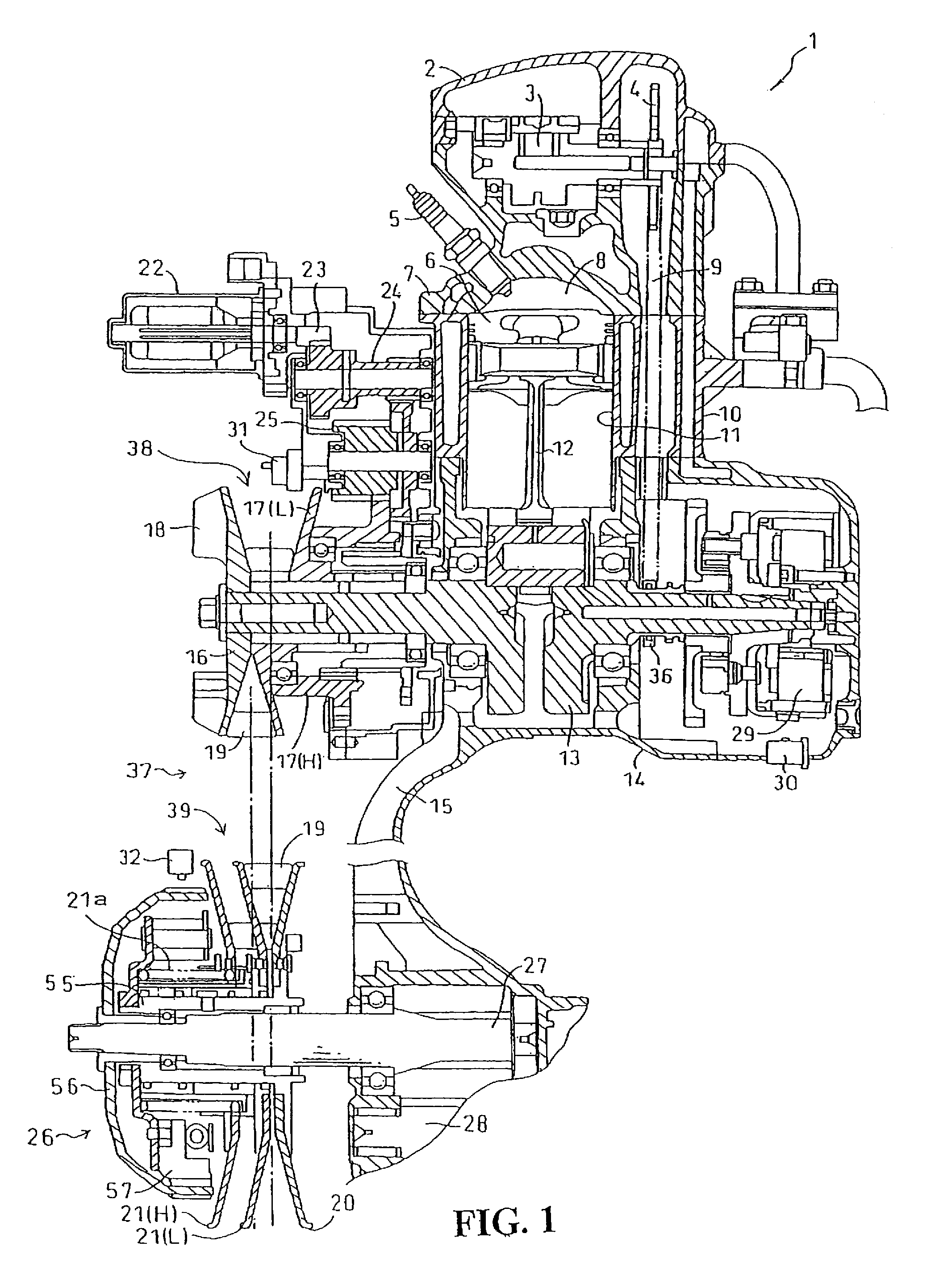
[0031]FIG. 1 shows a cross-sectional view of a power unit of a scooter-type motorcycle, which adopts an automatic transmission control device according to an embodiment of the present invention. A unit-swing type power unit 1 which is integrally constituted of an engine and a continuously variable transmission which transmits a driving force of the engine to a driving wheel at a proper gear ratio is, assuming the lateral direction in the drawing as the vehicle width direction, connected to a pivot portion arranged on a rear portion of the scooter-type motorcycle in a rockable manner. A piston 6 is connected to a crankshaft 13 which constitutes an output shaft of the engine by way of a connecting rod 12, and th...


PUM


Abstract

An automatic transmission control device of a vehicle performs a gear change operation based on a deceleration of the vehicle. The automatic transmission control device detects the deceleration of the vehicle and an engine rotational speed. The device also stores a peak value of the engine rotation speed during a period in which a vehicle travels with one predetermined gear step, and includes a relationship map showing the relationship between the deceleration and a shift-down rotational speed. The device performs an automatic shift-down when the engine rotational speed is lowered from the peak value by a predetermined rotational speed which is obtained from the map based on the deceleration.

Description

TECHNICAL FIELD[0001]The present invention relates to an automatic transmission control device, and more particularly to an automatic transmission control device which can obtain proper shift-down timing by accounting for deceleration and engine rotational speed.BACKGROUND OF THE INVENTION[0002]A conventional automatic transmission for a vehicle is known that induces a gear change rotational speed from a predetermined map based on a vehicle speed and a throttle opening and automatically performs a gear change operation based on the gear change rotational speed. There has also been known a transmission control device which, when it is determined that the deceleration of a vehicle body exceeds a predetermined value using a deceleration brake which is mounted on a wheel or the like, performs the shift-down to a gear change step which can obtain larger engine brake irrespective of the above-mentioned predetermined map.[0003]For example, JP-A-9-42433 1 discloses such a transmission contr...

Claims


Application Information

Patent Timeline
Patent Type & Authority Patents(United States)
IPC IPC(8): B60W10/06B60W10/10F16H59/42F16H59/48F16H61/04F16H61/66F16H61/662
CPCF16H61/0213F16H61/21F16H61/66259F16H59/48F16H59/54F16H61/66Y10S477/904F16H2061/0237F16H2061/6616Y10T477/692Y10T477/623Y10T477/688
Inventor MATSUDAIRA, NAOTADAUCHIDA, SOYAMORITA, GO
Owner HONDA MOTOR CO LTD
Why Eureka
Try Eureka