Frequency and timing synchronization and error correction in a satellite network

a satellite network and frequency and timing synchronization technology, applied in the field of frequency and timing synchronization and error correction in a satellite network, can solve problems such as limited initial frequency errors, for instance, and achieve the effects of simplifying installation, efficient use of satellite bandwidth resources, and large initial frequency errors

Inactive Publication Date: 2008-12-30
GILAT SATELLITE NETWORKS
View PDF8 Cites 5 Cited by
  • Summary
  • Abstract
  • Description
  • Claims
  • Application Information

AI Technical Summary

Benefits of technology

[0008]Therefore, aspects of the present invention allow for eliminating the periodic distribution over the forward channel of synchronization data (e.g., time stamps), for slot and / or frame synchronization of the return channel. Instead, slot and / or frame synchronization information is re-constructed at the remote terminal from the re-constructed reception data clock, its derivatives—byte clock, the MPEG Sync pulse (a pulse that occurs at the beginning of each 188-byte MPEG block), etc., and / or the re-constructed symbol clock (derived from, e.g., the baud rate of the received data) and its derivatives, and / or by proper burst timing error and burst frequency error feedback information from the hub. This is possible by using receivers configured to be able to receive initial bursts that are not necessarily aligned with time-slots, and by using timing feedback correction messages sent to the remote terminals from the hub.
[0009]According to further aspects of the present invention, efficient usage of satellite bandwidth resources may be maintained, while the incorporation of low-cost terminals with large initial frequency error is supported. This is possible by using receivers configured to be able to receive initial bursts that are not necessarily aligned with channel frequencies, and by using frequency feedback correction messages sent to the remote terminals from the hub. Furthermore, the system may support unknown geographic location of remote terminals, thus simplifying installations, and easing the support of transportable terminals.
[0010]Still further aspects of the present invention allow large initial burst-timing errors, and / or large initial burst frequency errors. Such initial frequency errors may, for instance, be limited only by the entire return-channel total bandwidth allocation. Thus, low cost transmitters, such as dielectric resonant oscillator (DRO)-based transmitters, with large initial frequency offsets, may now be more practically utilized in remote terminals.
[0011]Still further aspects of the present invention allow remote terminals to successfully operate even without prior knowledge of the remote terminal's geographical location or the delay of its transmission to the satellite or to the hub. This is because initial burst-timing alignment is not required. This greatly simplifies installation of remote terminals and increases their robustness. This feature of independence from geographical location may also be useful for incorporating mobile or transportable remote terminals into a satellite network.
[0012]There is also a need to reduce the potential for frequency error in outgoing transmissions from remote terminals. Although aspects of the present invention are discussed with regard to remote terminals, such aspects may be used in any communications equipment such as in satellites or hubs.

Problems solved by technology

Such initial frequency errors may, for instance, be limited only by the entire return-channel total bandwidth allocation.

Method used


Image

  • Frequency and timing synchronization and error correction in a satellite network
  • Frequency and timing synchronization and error correction in a satellite network
  • Frequency and timing synchronization and error correction in a satellite network

Examples


Embodiment Construction

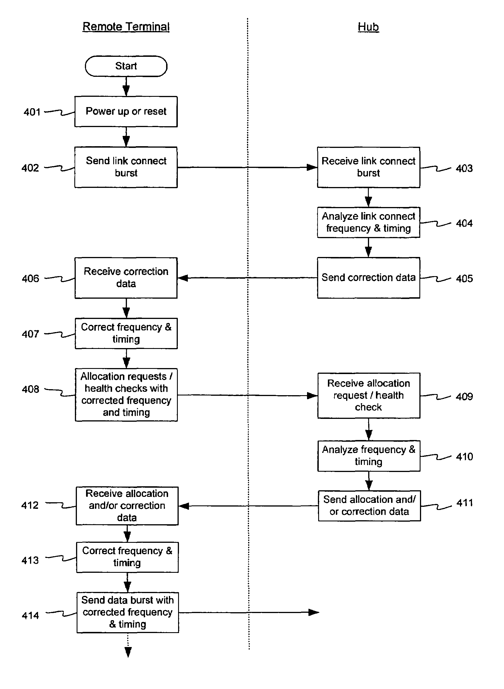
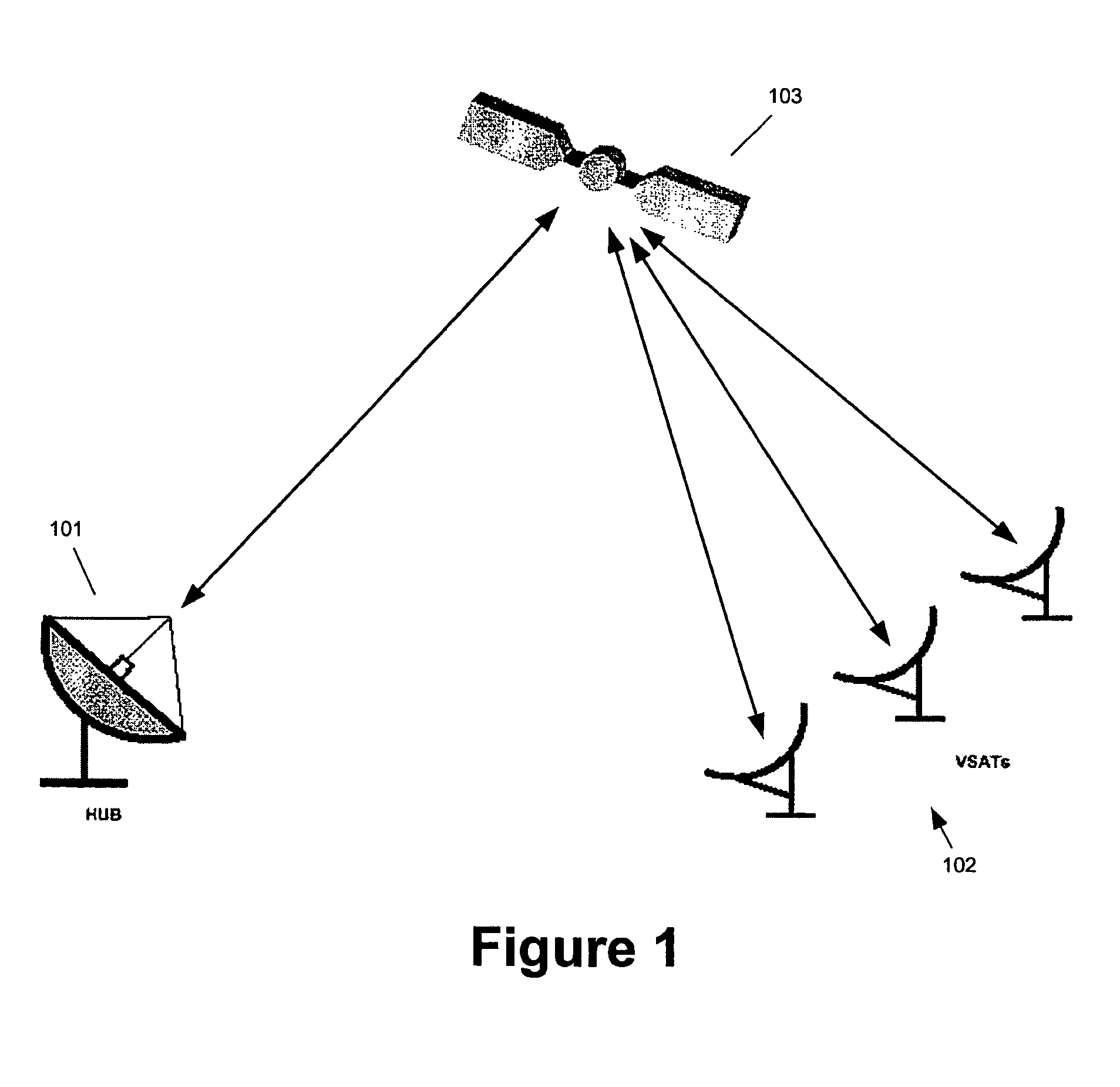
[0022]FIG. 1 shows an illustrative satellite network including a satellite 103, a hub 101, and a plurality of remote terminals 102 such as, but not limited to, VSATs. The hub 101 and the remote terminals 102 as shown embody a two-way data network in a star configuration. Messages from the hub 101 to the remote terminals 102 may be sent via a TDM signal on a forward or outbound channel that is broadcast to some or all of the remote terminals (“multicast” messages). Messages to specific ones of the remote terminals 102 (“unicast” messages) may also be multiplexed along with the “multicast” messages. The hub 101 may transmit via a standard DVB-S carrier, and may include a local DVB-S receiver that receives its own outbound transmission. The output data from the DVB-S receiver may be a standard MPEG transport stream.

[0023]The data from the remote terminals 102 to the hub 101 may be sent as a series of burst transmissions. Multiple access to the shared frequency-time resources may be imp...


PUM


Abstract

An outgoing transmission carrier frequency at, for example, a remote terminal, may be adjusted based on a feature rate of an incoming transmission. The adjustment may compensate for error in the outgoing transmission carrier frequency. The incoming transmission may be from a satellite or hub, for example. The outgoing transmission may be the signal that is transmitted by an antenna, or the outgoing transmission may be converted to be at another carrier frequency such as a higher carrier frequency for ultimate transmission by an antenna. Also, a remote terminal may be synchronized to a satellite network with or without knowledge of the remote terminals' geographical location and with or without time stamps.

Description

CROSS-REFERENCE TO RELATED APPLICATIONS[0001]The present application claims priority to U.S. Provisional patent Application Ser. No. 60 / 472,727, entitled “Satellite Frequency and Timing Synchronization and Correction,” filed May 23, 2003, incorporated by reference herein as to its entirety.BACKGROUND OF THE INVENTION[0002]The most common topology of a satellite network is the star topology, in which a central hub broadcasts toward a plurality of remote terminals (such as very small aperture terminals, or VSATs) via a forward time-domain multiplexed (TDM) carrier, and the remote terminals communicate with the hub by return channel bursts. There are many common multiple access schemes, the choice of which involves a dilemma and a well-known trade-off. Contention-based random access (CRA) solutions, such as Slotted Aloha, tend to have short response-time per transaction. However, the throughput is limited theoretically to about 36% utilization of the available channel. Moreover, in ord...

Claims


Application Information

Patent Timeline
Patent Type & Authority Patents(United States)
IPC IPC(8): H04B3/36H04B7/185H04B7/208H04B7/212
CPCH04B7/18528H04B7/208H04B7/2125
Inventor RAM, UZIKESHET, ARIKKESCHET, DANIEL
Owner GILAT SATELLITE NETWORKS
Why Eureka
Try Eureka