Flyer and spindle brake assembly for handspinning wheels

a technology of hand-spinning wheels and brake assemblies, which is applied in the direction of drafting machines, continuous wounding machines, and paper and paper products, etc., can solve the problems of inability to take up the bobbin, inconvenient operation, and inability to use the bobbin

Inactive Publication Date: 2009-01-06
BRUNK KENNETH D
View PDF23 Cites 8 Cited by
  • Summary
  • Abstract
  • Description
  • Claims
  • Application Information

AI Technical Summary

Benefits of technology

[0015]The device is used by initially drawing the flyer axially outwardly away from the maiden post by compressing the flyer retaining spring, thereby freeing the distal end of the spindle from the spindle bearing of the flyer. The flyer is then pivoted about its attachment points at the collar, thereby clearing the distal end of the spindle for the installation of a spool or bobbin thereon. The flyer is then repositioned to secure the distal end of the spindle in the spindle bearing of the distal end of the flyer in order to align the components axially with one another. The spindle brake may be adjusted as desired. Spinning operations may then commence, with the rotating flyer twisting the yarn, thread, etc. therearound so long as the bobbin or spool is allowed to rotate in unison with the flyer. When a length of spun yarn or cord has been produced, the tension on the spun material is relaxed, thereby allowing the brake to slow the rotational speed of the spindle and bobbin installed thereon. This results in the spun material being wound upon the relatively slowly spinning or stopped bobbin, as the flyer continues to rotate around the spindle and bobbin. Further tension on the fiber material overcomes the spindle brake, and causes the bobbin and spindle to rotate in unison with the flyer to twist another length of yarn, thread, or similar material. The process is repeated as desired, with the brake mechanism being adjusted as required for optimum operation.

Problems solved by technology

However, such manually powered spinning machines or spinning wheels are still popular today in many parts of the world where electricity or other power is generally not available, or where the use of such power is not desired for some reason.
Secondly, as a length of twisted material is produced, the machine is used to take up the twisted yarn onto a spool or bobbin for storage.
Thus, even though the yarn or thread is being spun around the bobbin by the rotation of the flyer, it cannot be taken up on the bobbin, as the bobbin is rotating at the same rate.
Moreover, such an open-ended flyer structure is relatively weak in comparison to a closed flyer, which completely surrounds the bobbin.
This requires a fair amount of time for each bobbin removal and replacement, as well as increasing the cost of the mechanism and the chance of losing various small parts.
However, in the past it has proven difficult to provide a bobbin or spindle brake that may be easily and precisely adjusted to produce exactly the desired braking force.
While a relatively large amount of effort has gone into the development of spindle and / or bobbin brakes for large, automated industrial spinning and winding machines and looms, comparatively little development has occurred in spindle or bobbin brake systems in manually or treadle operated spinning wheels.
Conventional bobbin or spindle brakes tend to be relatively primitive devices, and generally fail to provide the required degree of fine adjustment for accurate work.

Method used


Image

  • Flyer and spindle brake assembly for handspinning wheels
  • Flyer and spindle brake assembly for handspinning wheels
  • Flyer and spindle brake assembly for handspinning wheels

Examples


Embodiment Construction

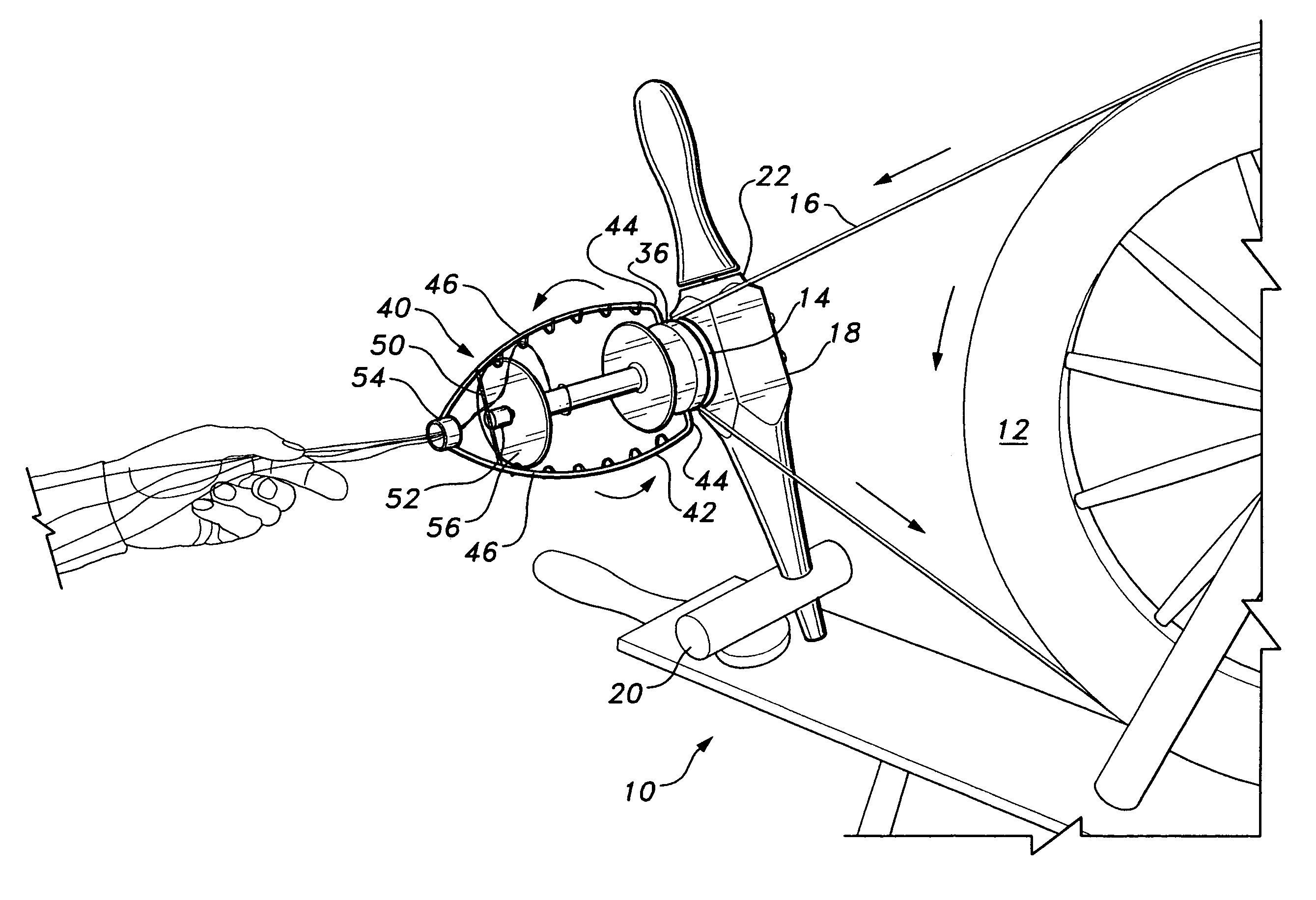
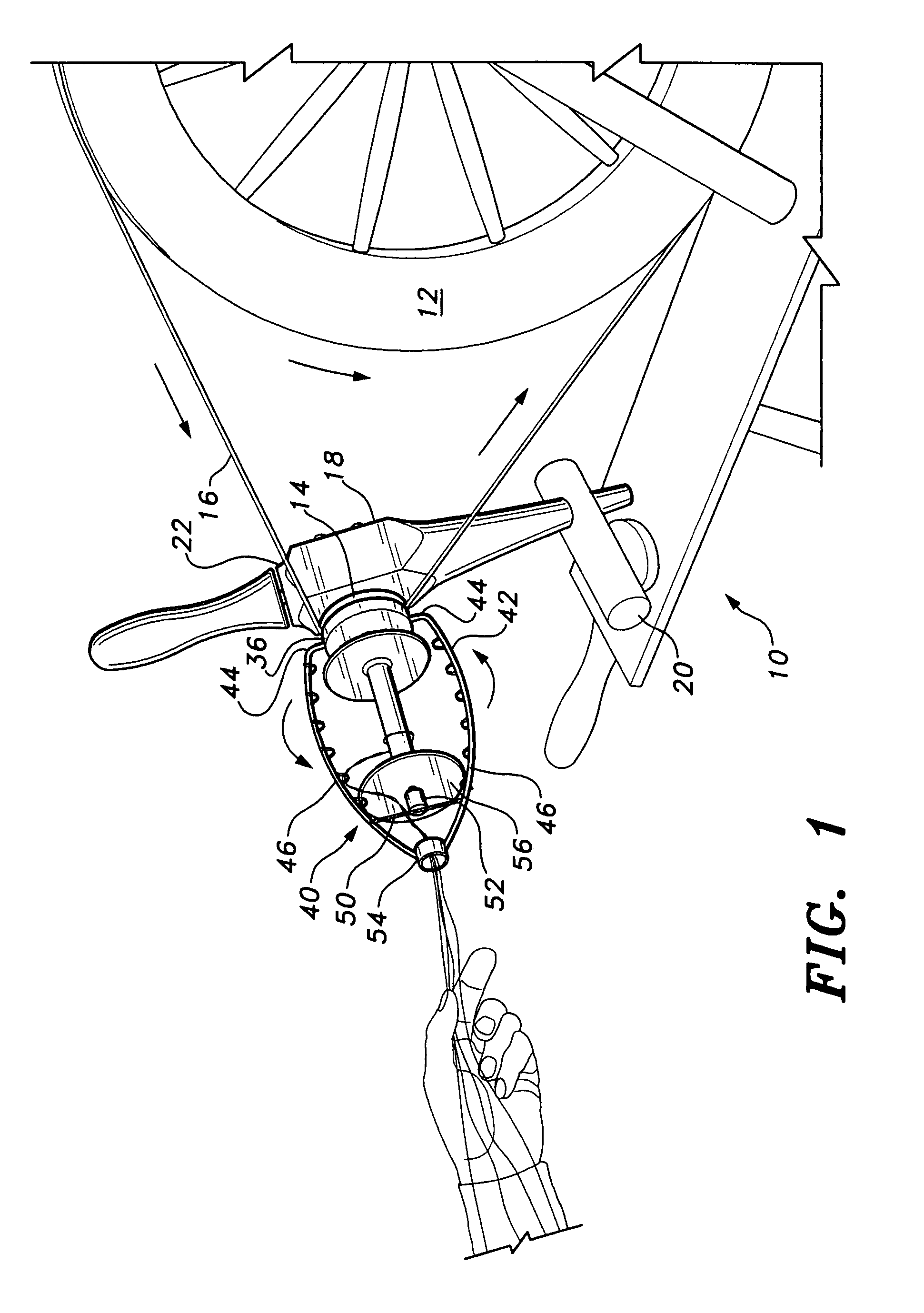
[0022]The present invention is related to the hand spinning wheel, in particular, a flyer or bail that obviates the need to remove components for access to the bobbin or spool, and a spindle brake device. The flyer and the brake assembly allow the person spinning yarn or thread to remove and replace the bobbin or spool much more rapidly than is the case with conventional systems, and further to more precisely adjust the spindle braking mechanism for more accurate control of the yarn or thread takeup.

[0023]FIG. 1 of the drawings provides an environmental perspective view of a portion of a spinning wheel assembly 10 having the flyer and spindle mechanism of the present invention installed thereon. The spinning wheel 10 includes a conventional flywheel or drive wheel 12, which is typically driven by a conventional treadle and crank system, or alternatively spun by hand, or in some other manner. The drive wheel 12 drives a whorl or spindle pulley 14 by means of a drive belt 16 extending...


PUM

PropertyMeasurementUnit
pressureaaaaaaaaaa
lengthaaaaaaaaaa
rotary speedaaaaaaaaaa

Abstract

The flyer and spindle brake assembly for hand spinning wheels includes a cantilevered spindle and flyer assembly extending from a single maiden post. The spindle base is secured in an adjustable brake mechanism installed in the upper end of the maiden. The flyer has a closed distal end with a spindle bearing and yarn orifice. The flyer is urged toward its whorl or drive pulley by a coil spring on the spindle. The flyer is pulled axially outwardly away from the whorl to release the distal end of the spindle therefrom, the flyer then pivoting from the spindle axis for installation or removal of a bobbin or spool on the spindle. The brake mechanism provides extremely fine and accurate adjustment of braking force for the spindle and spool, while the flyer mechanism allows removal and installation of a spool on the spindle without the need for disassembly of components.

Description

CROSS-REFERENCE TO RELATED APPLICATION[0001]This application claims the benefit of U.S. Provisional Patent Application Ser. No. 60 / 872,476, filed Dec. 4, 2006.BACKGROUND OF THE INVENTION[0002]1. Field of the Invention[0003]The present invention relates generally to manually and / or treadle operated spinning wheels. More specifically, the invention relates to a flyer and spindle brake assembly for hand spinning wheels.[0004]2. Description of the Related Art[0005]Hand spinning wheels, i.e., yarn, thread, or other fiber spinning or twisting machines utilizing manual power for their operation, have a lengthy history. Historically, such wheels were used to produce the vast majority of spun fiber material (yarn, thread, and other fiber for cloth, etc.) until the development of large, powered industrial spinning machines. However, such manually powered spinning machines or spinning wheels are still popular today in many parts of the world where electricity or other power is generally not av...

Claims


Application Information

Patent Timeline
Patent Type & Authority Patents(United States)
IPC IPC(8): D01H5/28
CPCD01H1/00D01H1/04D01H7/22D01H7/24D01H7/42
Inventor BRUNK, KENNETH D.
Owner BRUNK KENNETH D
Why Eureka
Try Eureka