Valve control device and valve control method for internal combustion engine

a valve control device and internal combustion engine technology, applied in electric control, machines/engines, mechanical equipment, etc., can solve the problems of large change in intake air volume, torque shock, and insufficient so as to promote homogenization of air-fuel mixture and simplify control and structure.

Inactive Publication Date: 2009-01-06
DENSO CORP
View PDF6 Cites 16 Cited by
  • Summary
  • Abstract
  • Description
  • Claims
  • Application Information

AI Technical Summary

Benefits of technology

[0008]It is an object of the present invention to provide a valve control device or / and a valve control method for an internal combustion engine, which can promote homogenization of an air-fuel mixture in all operation areas, and also can simplify the control and structure thereof.
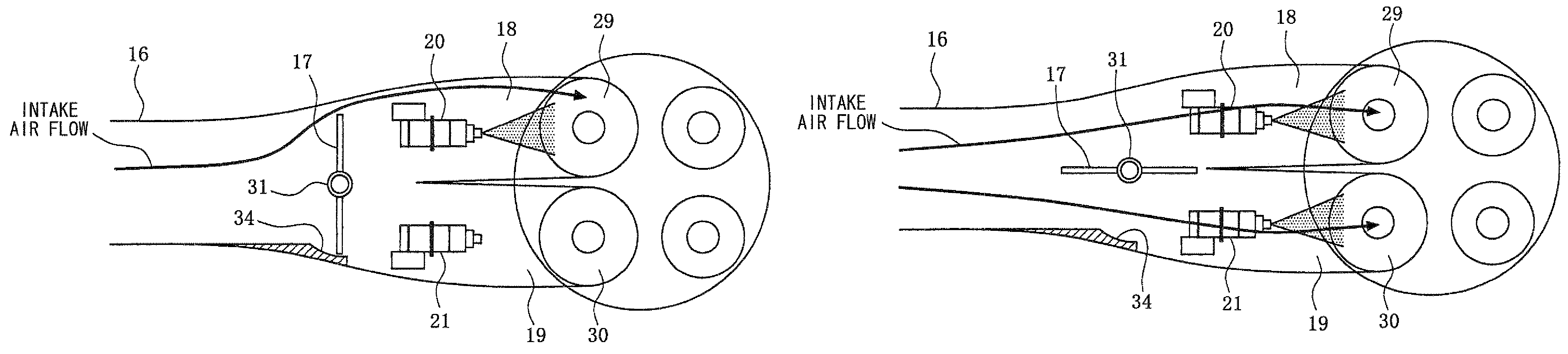
[0010]With this arrangement, when the opening degree of the intake throttle valve is substantially equal to or less than the predetermined value, the intake air mainly flows through the first intake port to generate a swirl flow in the cylinder, while the fuel is injected from the first fuel injection valve to the first intake port Thus, it can promote the homogenization of an air-fuel mixture. In contrast, when the opening degree of the intake throttle valve is substantially larger than the predetermined value, the intake air flows through both of the first and second intake ports, while the fuel is injected from both the first and second fuel injection valves to the respective first and second intake ports. Thus, it can also promote the homogenization of an air-fuel mixture. As a result, the homogenization of the air-fuel mixture can be promoted in all operation areas from a low load operation area where an opening degree of the intake throttle valve is small to a high load operation area where an opening degree of the intake throttle valve is large.
[0011]Since the intake air amount can be adjusted according to the opening degree of the intake throttle valve to control the occurrence of the swirl flow, the drastic change (torque shock) of the intake air amount hardly occurs due to the opening and closing of the intake throttle valve. In order to prevent the drastic change of the intake air amount, a complicated control is also not required, thereby simplifying the control of the intake throttle valve.
[0012]Since the intake throttle valve can have a function of adjusting the amount of intake air, and also a function of generating a swirl flow, a valve for adjusting the intake air amount and a valve for generating the swirl flow do not need to be provided independently, thereby simplifying the structure and satisfying the demand for cost reduction.
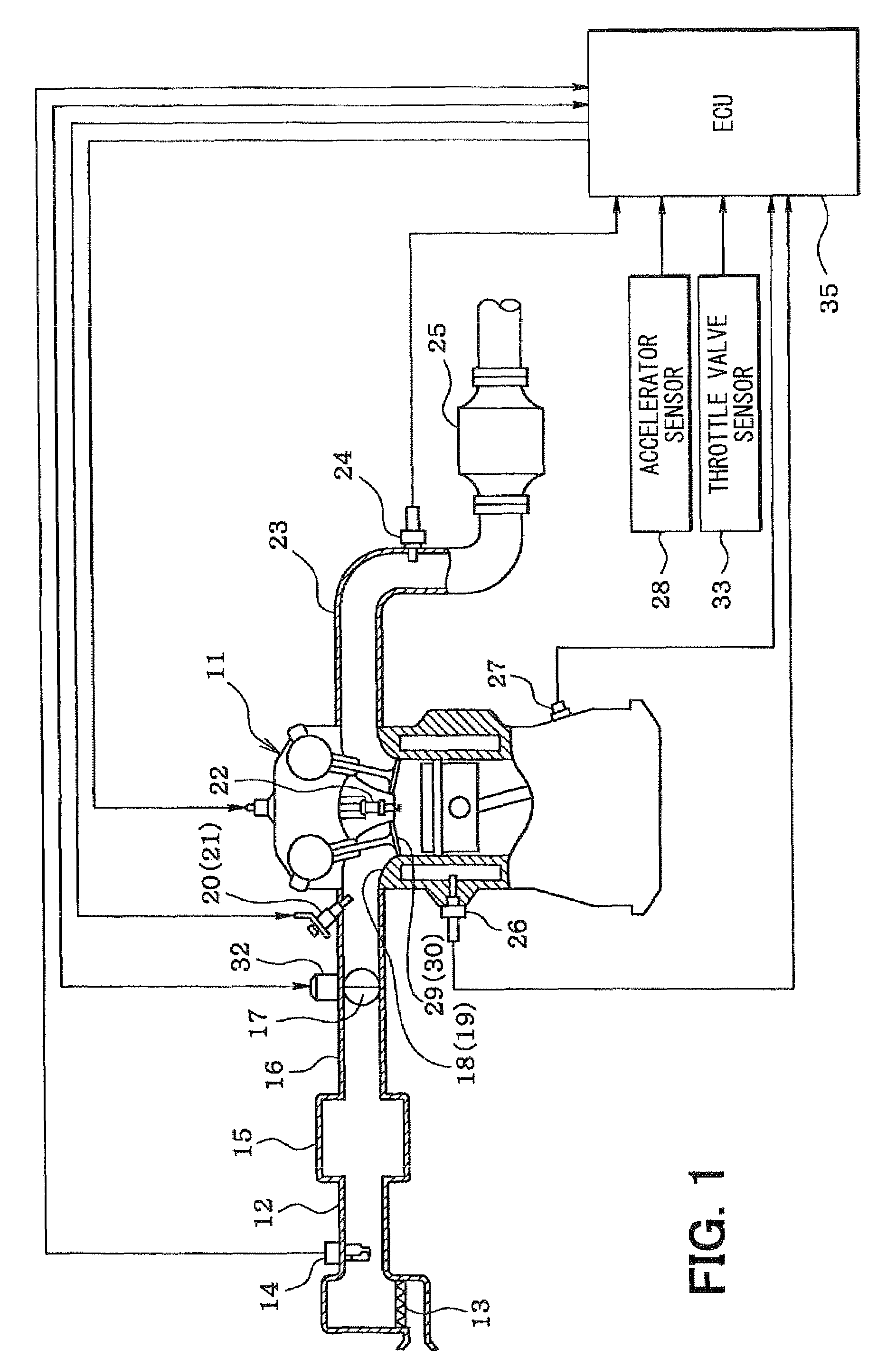
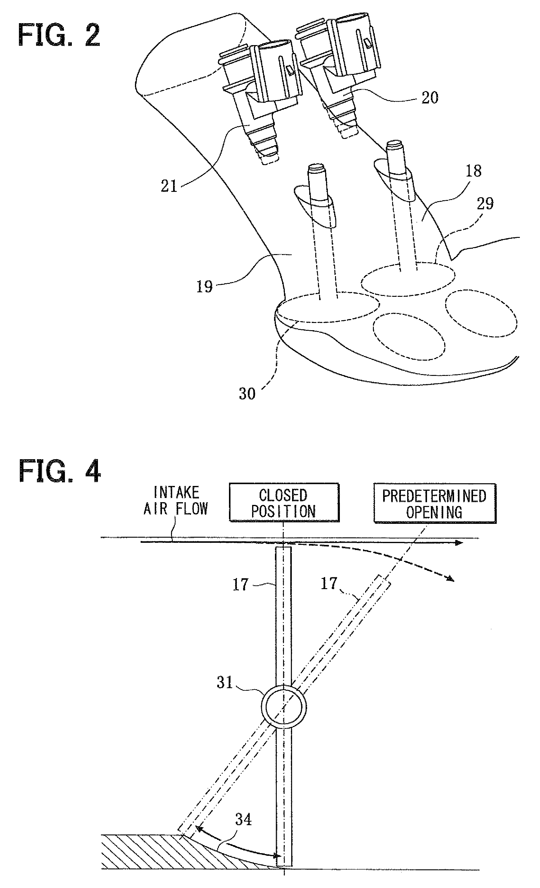
[0013]According to another aspect of the present invention, a valve control device for an internal combustion engine includes an intake manifold for defining an intake air passage having first and second intake ports which are located at a downstream side of the intake air passage for each cylinder of the engine, an intake throttle valve located in the intake air passage at an upstream side of the first and second intake ports, a first fuel injection valve located to inject fuel to the first intake port, and a second fuel injection valve located to inject the fuel to the second intake port. The intake throttle valve is located such that intake air flows into mainly the first intake port to generate a swirl flow when an opening degree of the intake throttle valve is not larger than a predetermined value, and flows into both the first and second intake ports when the opening degree of the intake throttle valve is larger than the predetermined value, and a control unit controls the first fuel injection valve and the second fuel injection valve in accordance with the opening degree of the intake throttle valve. Furthermore, a bore member is located in the intake air passage at a position adjacent to the intake throttle valve to prohibit a flow of the intake air to the second intake port when the opening degree of the intake throttle valve is not larger than the predetermined value. Accordingly, it is possible to control the swirl flow from the first intake port while keeping a substantially closing state of the second intake port when the opening degree of the intake throttle valve is not larger than the predetermined value. As a result, it can promote homogenization of the air-fuel mixture in all operation areas, and also can simplify the structure in the intake manifold.
[0015]According to another aspect of the present invention, a valve control method for an internal combustion engine includes a step of detecting an opening degree of an intake throttle valve that located in the intake air passage at an upstream side of the first and second intake ports, a step of determining whether the opening degree of the intake throttle valve is larger than a predetermined value, a step of controlling the intake throttle valve such that intake air flows into mainly the first intake port to generate a swirl flow when the opening degree of the intake throttle valve is not larger than a predetermined value, and flows into both the first and second intake ports when the opening degree of the intake throttle valve is larger than the predetermined value, and a step of controlling a first fuel injection valve and a second fuel injection valve to allow an injection of the fuel from the first fuel injection valve into the first intake port when the opening degree of the intake throttle valve is not larger than about the predetermined value, and a step of controlling the first fuel injection valve and the second fuel injection valve to allow injections of the fuel from both the first fuel injection valve and the second fuel injection valve when the opening degree of the intake throttle valve is larger than about the predetermined value. Accordingly, the homogenization of the air-fuel mixture can be promoted in all operation areas from a low load operation area where an opening degree of the intake throttle valve is small to a high load operation area where an opening degree of the intake throttle valve is large.

Problems solved by technology

In such a system, when switching operations between opening and closing of the swirl control valves of the respective cylinders are performed at the same time in a transient operation for switching between opening and closing of the swirl control valve, the amount of intake air may greatly change to cause torque shock.
In this case, the air-fuel mixture cannot be sufficiently homogeneous.
This leads to complicated control of the swirl control valves, resulting in increased computation load of a control computer.
Furthermore, because a throttle valve for adjusting the amount of intake air and a swirl control valve for generating the swirl flow are required to be provided independently, the valve structure becomes complicated, resulting in an increase in cost.

Method used


Image

  • Valve control device and valve control method for internal combustion engine
  • Valve control device and valve control method for internal combustion engine
  • Valve control device and valve control method for internal combustion engine

Examples


Embodiment Construction

[0023]The outline of the entire structure of an engine control system will be described below based on FIG. 1.

[0024]An air cleaner 13 is provided on an uppermost stream side of an intake pipe 12 of an engine 11, which is an internal combustion engine, for example. An air flow meter 14 for detecting an amount of intake air is provided on a downstream side of the air cleaner 13. A surge tank 15 is provided on a downstream side of the air flow meter 14. An intake manifold 16 (intake passage) is provided in the surge tank 15, for introducing the air into each cylinder of the engine 11. An intake throttle valve 17 for adjusting an amount of intake air is provided in the intake manifold 16 of each cylinder. Fuel injection valves 20 and 21 for injecting fuel therefrom are attached near two intake ports 18 and 19 of each cylinder (see FIGS. 2, 3A, and 3B). An ignition plug 22 is attached for each cylinder to a cylinder head of the engine 11. Spark discharge of each ignition plug 22 ignites ...


PUM


Abstract

An intake throttle valve is located in an intake passage upstream of first and second intake ports, such that intake air flows into mainly the first intake port to generate a swirl flow when an opening degree of the intake throttle valve is not larger than a predetermined value, and flows into both the first and second intake ports when the opening degree thereof is larger than the predetermined value. Furthermore, first and second fuel injection valves for respectively injecting fuel to the first and second intake ports are controlled to inject fuel from the first fuel injection valve when the opening degree of the intake throttle valve is not larger than about the predetermined value, and to inject fuel from both the first fuel injection valve and the second fuel injection valve when the opening degree of the intake throttle valve is larger than about the predetermined value.

Description

CROSS REFERENCE TO RELATED APPLICATION[0001]This application is based on Japanese Patent Application No. 2006-293398 filed on Oct. 30, 2006, the contents of which are incorporated herein by reference in its entirety.FIELD OF THE INVENTION[0002]The present invention relates to a valve control device for an internal combustion engine, which includes an intake throttle valve and two intake ports in one cylinder, and a valve control method for the internal combustion engine.BACKGROUND OF THE INVENTION[0003]For example, in JP-A-8-121180, a throttle valve for adjusting an amount of intake air is disposed in an intake pipe on the upstream side from an intake manifold of each cylinder of an internal combustion engine. Further, a swirl control valve is disposed in a passage on one intake port side of two intake ports provided in each cylinder, while a fuel injection valve is disposed in a passage on the other intake port side. During a low or medium load operation in which the amount of inta...

Claims


Application Information

Patent Timeline
Patent Type & Authority Patents(United States)
IPC IPC(8): F02B3/00F02B15/00
CPCF02B31/02F02B31/06F01L1/34F01L2001/0537Y02T10/146F02D41/3094Y02T10/12
Inventor YAMASHITA, HIROSHISUZUKI, HIDEKI
Owner DENSO CORP
Why Eureka
Try Eureka