Well cleanup tool with real time condition feedback to the surface

a technology of surface condition and cleanup tool, which is applied in the direction of earthwork drilling tools, borehole/well accessories, survey, etc., can solve the problems of screen b>34/b> clogging with debris, and not always going downhole right,

Active Publication Date: 2009-01-06
BAKER HUGHES INC
View PDF53 Cites 61 Cited by
  • Summary
  • Abstract
  • Description
  • Claims
  • Application Information

AI Technical Summary

Problems solved by technology

However, things don't always go right downhole and the operator at the surface using this tool in a milling operation had no information that things downhole may not be going according to plan.
The main two things that can cause problems with this type of tool or any other junk basket tool is that the screen 34 can clog with debris.
As a result, there is a diminished or a total lack of flow into the mill ports to remove the cuttings and take away the heat of milling.
The mill can overheat or get stuck in cuttings or both.
If the mill sticks and turning force is still applied from the surface, the connections to the mill can fail.
While some operator with enough experience cleaning up a hole may be able to do this by gut feel in certain situations like removing sand, using gut feel is not reliable and in milling as opposed to simple debris cleanout, rules of thumb about how fast the bottom hole assembly moves into sand when removing it from the wellbore are simply useless.

Method used


Image

  • Well cleanup tool with real time condition feedback to the surface
  • Well cleanup tool with real time condition feedback to the surface
  • Well cleanup tool with real time condition feedback to the surface

Examples


Embodiment Construction

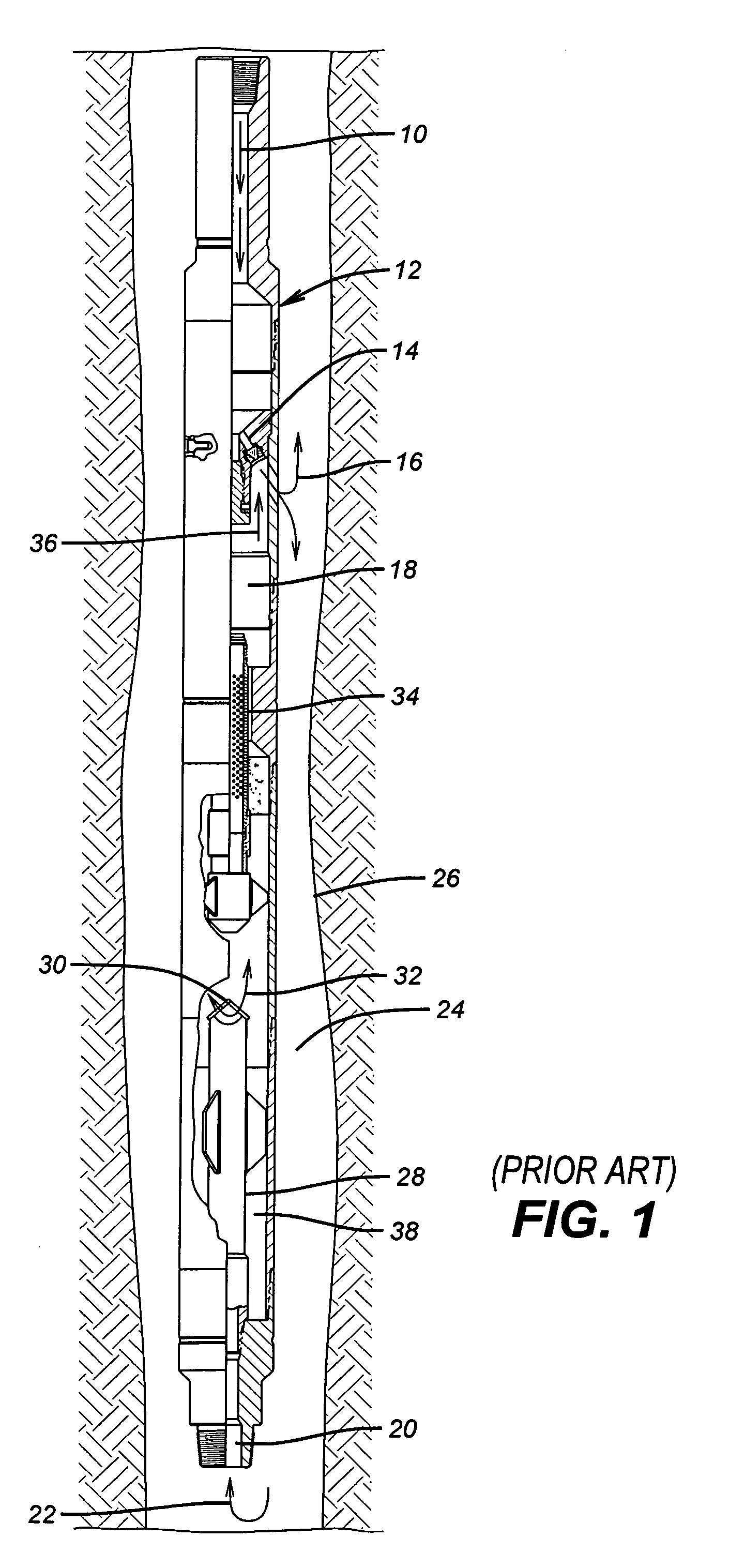
[0017]The operation of one type of such tool is illustrated in FIG. 1. In this known tool, flow comes from the surface through a string (not shown) and enters passage 10 in the tool 12. Flow goes through the eductor 14 and exits as shown by two headed arrow 16. Arrow 16 indicates that the exiting motive fluid can go uphole and downhole. The eductor 14 reduces pressure in chamber 18 all the way down to the mill and lower inlet schematically represented as 20 on the tool 12. Arrow 22 represents fluid indicated by arrow 16 that has traveled down the annulus 24 between tool 12 and tubular 26 as well as well fluid below tool 12 that is sucked in due to the venturi effect of the eductor 14. Entering fluid at lower inlet 20 goes through a tube 28 that has a hat with openings under it 30. Arrows 32 indicate the exiting flow out from under hat 30 that next goes to the outside of screen 34. At this point the cuttings are stopped by the screen 34 while the fluid goes on through and into chambe...


PUM


Abstract

A flow sensor is incorporated into a junk basket to sense a flow stoppage due to a plugged screen or plugged cuttings ports in a mill. The sensor triggers a signal to the surface to warn personnel that a problem exists before the equipment is damaged. The sensor signal to the surface can take a variety of forms including mud pulses, a detectable pressure buildup at the surface, electromagnetic energy, electrical signal on hard wire or radio signals in a wifi system to name a few options. Surface personnel can interrupt the signal to take corrective action that generally involves pulling out of the hole or reverse circulating to try to clear the screen or mill cuttings inlets. Other variables can be measured such as the volume or weight or rate of change of either and a signal can be sent to the surface corresponding to one of those variables to allow them to be detected at the surface in near real time.

Description

FIELD OF THE INVENTION[0001]The field of this invention relates to well cleanup tools that collect debris and more particularly tools that collect cuttings from milling using an eductor to draw them into the tool body.BACKGROUND OF THE INVENTION[0002]When milling out a tool or pipe in the well cuttings are generated that need to be removed from the milling site and collected. The bottom hole assembly that includes the mill also has what is sometimes referred to as a junk basket. These tools operate on different principles and have the common objective of separation of circulating fluid from the cuttings. This is generally done by directing the flow laden with cuttings into the tool having a catch chamber. The fluid is directed through a screen, leaving the cuttings behind. At some point the cuttings fall down into the collection volume below and outside the screen.[0003]The operation of one type of such tool is illustrated in FIG. 1. In this known tool, flow comes from the surface t...

Claims


Application Information

Patent Timeline
Patent Type & Authority Patents(United States)
IPC IPC(8): E21B31/08E21B12/00E21B27/00
CPCE21B27/005E21B29/00E21B47/12E21B47/18E21B29/002
Inventor LYNDE, GERALD D.DAVIS, JOHN P.ROSENBLATT, STEVE
Owner BAKER HUGHES INC
Why Eureka
Try Eureka