Well cleanup tool with real time condition feedback to the surface

a technology of condition feedback and well cleanup, which is applied in the direction of fluid removal, borehole/well accessories, survey, etc., can solve the problems of screen b>34/b> clogging with debris, and not always going downhole right,

Active Publication Date: 2007-11-29
BAKER HUGHES INC
View PDF39 Cites 42 Cited by
  • Summary
  • Abstract
  • Description
  • Claims
  • Application Information

AI Technical Summary

Benefits of technology

[0013]FIG. 6 is an alternative to FIG. 5 where a system of wireless commun...

Problems solved by technology

However, things don't always go right downhole and the operator at the surface using this tool in a milling operation had no information that things downhole may not be going according to plan.
The main two things that can cause problems with this type of tool or any other junk basket tool is that the screen 34 can clog with debris.
As a result, there is a diminished or a total lack of flow into the mill ports to remove the cuttings and take away the heat of milling.
The mill can overh...

Method used


Image

  • Well cleanup tool with real time condition feedback to the surface
  • Well cleanup tool with real time condition feedback to the surface
  • Well cleanup tool with real time condition feedback to the surface

Examples


Embodiment Construction

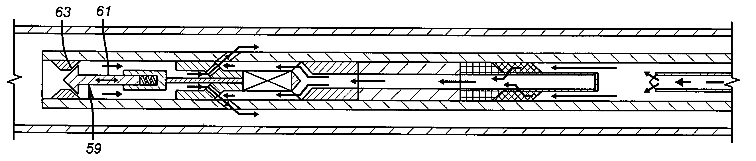
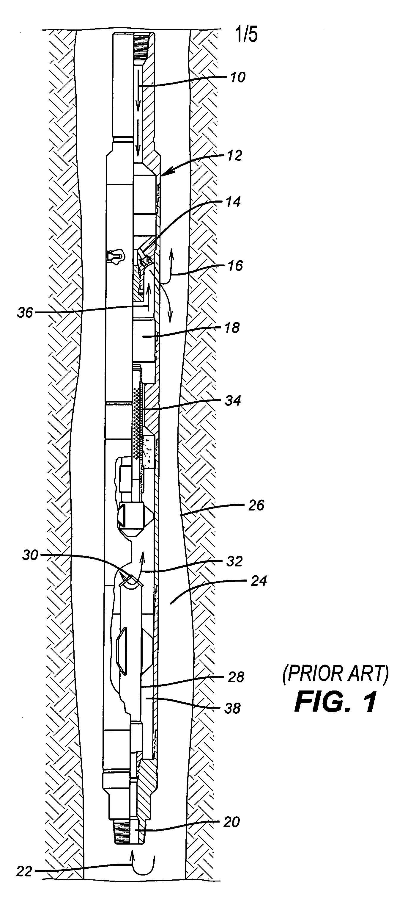
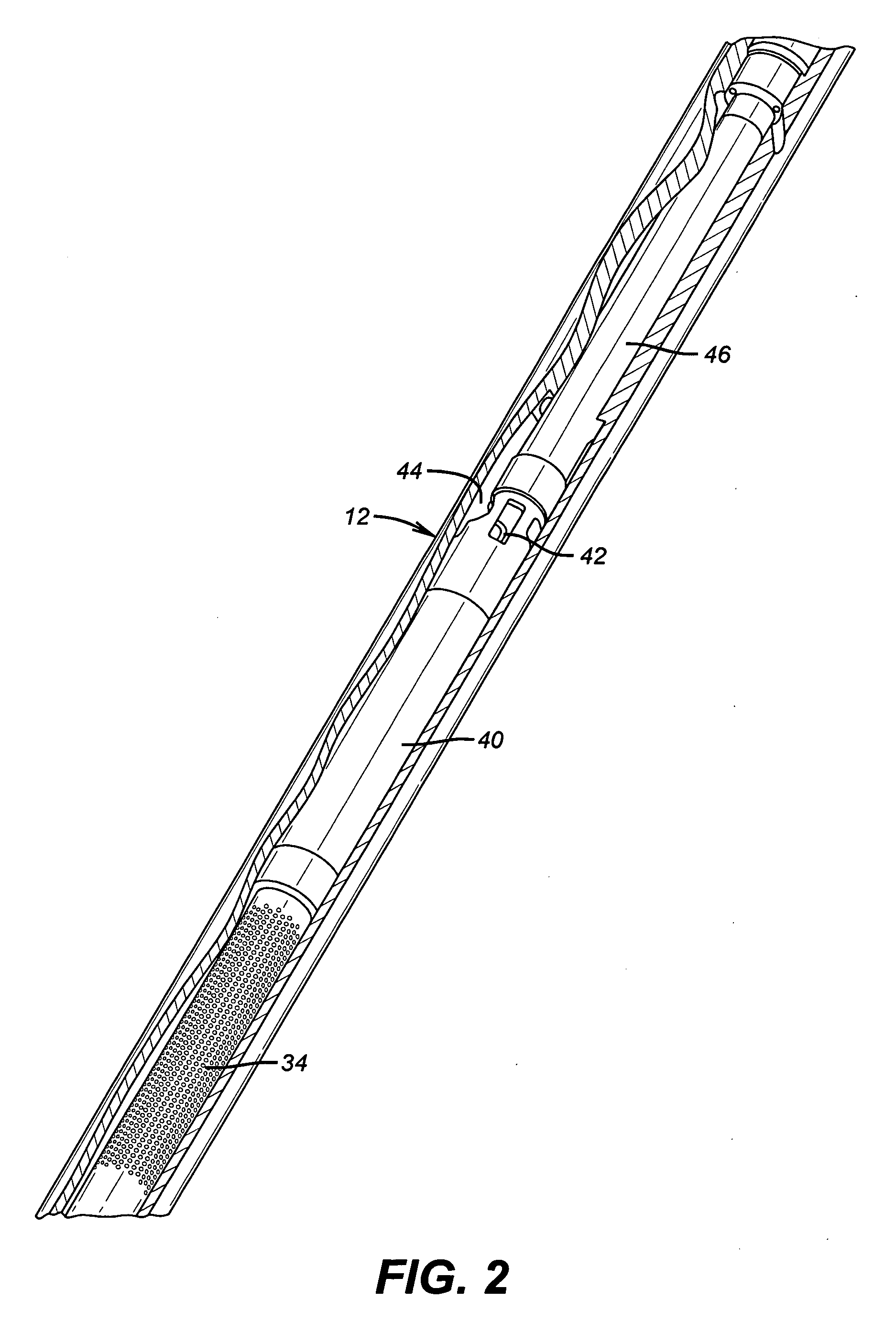
[0017]The junk basket 12 of FIG. 1 is modified as shown in FIGS. 2-4. A flow sensor 40 receives flow that has passed through the screen 34 leaving the cuttings outside the screen. After passing through the flow sensor that is designed to sense the flow while creating minimal additional pressure drop the flow goes through a crossover 42 and into annulus 44 within the tool 12. Located above the crossover 42 is a battery pack and motor generally referred to as 46. FIG. 3 shows the entire flow regime. The fluid passes first through screen 34 with the cleaner fluid then passing through the flow sensor. Next the flow goes through the crossover and into annulus 44 inside the tool 12 while bypassing the battery pack and motor 46. Passage 10 is illustrated at the left side of FIG. 3. The eductor 14 comprises aligned and preferably inclined openings 46 and 48. Normally pressurized flow from the surface enters passage 10 and rushes out through aligned ports 48 and 50. That rushing flow reduces...


PUM


Abstract

A flow sensor is incorporated into a junk basket to sense a flow stoppage due to a plugged screen or plugged cuttings ports in a mill. The sensor triggers a signal to the surface to warn personnel that a problem exists before the equipment is damaged. The sensor signal to the surface can take a variety of forms including mud pulses, a detectable pressure buildup at the surface, electromagnetic energy, electrical signal on hard wire or radio signals in a wifi system to name a few options. Surface personnel can interrupt the milling to take corrective action that generally involves pulling out of the hole or reverse circulating to try to clear the screen or mill cuttings inlets. Other variables can be measured such as the volume or weight or rate of change of either and a signal can be sent to the surface corresponding to one of those variables to allow them to be detected at the surface in real time.

Description

FIELD OF THE INVENTION[0001]The field of this invention relates to well cleanup tools that collect debris and more particularly tools that collect cuttings from milling using an eductor to draw them into the tool body.BACKGROUND OF THE INVENTION[0002]When milling out a tool or pipe in the well cuttings are generated that need to be removed from the milling site and collected. The bottom hole assembly that includes the mill also has what is sometimes referred to as a junk basket. These tools operate on different principles and have the common objective of separation of circulating fluid from the cuttings. This is generally done by directing the flow laden with cuttings into the tool having a catch chamber. The fluid is directed through a screen, leaving the cuttings behind. At some point the cuttings fall down into the collection volume below and outside the screen.[0003]The operation of one type of such tool is illustrated in FIG. 1. In this known tool, flow comes from the surface t...

Claims


Application Information

Patent Timeline
IPC IPC(8): E21B31/08
CPCE21B27/005E21B47/18E21B47/12E21B29/00E21B29/002
Inventor LYNDE, GERALD D.DAVIS, JOHN P.ROSENBLATT, STEVE
Owner BAKER HUGHES INC
Why Eureka
Try Eureka