Valve holding member

a technology of valves and holding parts, applied in the direction of suspension, couplings, machines/engines, etc., can solve the problems of large resistance to fluid flowing in the fluid passage, and achieve the effect of reducing the area of the hub part, stably holding, and reducing the flow resistance of the fluid passag

Active Publication Date: 2009-01-06
NITTO KOHKI CO LTD
View PDF12 Cites 4 Cited by
  • Summary
  • Abstract
  • Description
  • Claims
  • Application Information

AI Technical Summary

Benefits of technology

[0009]The present invention provides a valve holding member made of a single sheet metal for movably holding, along a fluid passage of a pipe coupling, a valve for opening and closing the fluid passage. The valve holding member includes a hub part having a guide hole through which a valve stem of the valve extends, and two arm parts diametrically opposing each other on the peripheral edge of the hub part and extending from the peripheral edge in the axial and radially outward direction with respect to the axis of the valve stem to securely engage with the peripheral wall of the fluid passage at distal end portions thereof.
[0017]Basically, in the valve holding member according to the present invention, the flow resistance of the fluid passage can be reduced compared with a conventional valve holding member by reducing the number of arm parts to two. Moreover, the distal end portion of each of the arm parts is widened, whereby the valve holding member can be stably held in the pipe coupling. Further, the hub part is composed of a circular portion and arm connecting portions, and thus the area of the hub part can be reduced relative to the cross section of the fluid passage, which can also reduce the flow resistance of the fluid passage. Furthermore, in a state in which the valve holding member is mounted in the pipe coupling, the interior angle between the hub part and each of the arm parts is approximately right, whereby it is possible to adequately maintain pressure resistance of the arm parts against a fluid force even if the valve holding member has only two arm parts. The valve holding member is provided with reinforcing structures, whereby it is possible to increase pressure resistance against a fluid even though the valve holding member is formed from a single sheet metal. The arm parts are each provided at the distal end edges thereof with a non-engagement portion, thereby being able to surely engage with the holding shoulder portion on the inner wall of the pipe coupling even if the arm parts are deformed.

Problems solved by technology

However, this sheet metal valve holding member needs three arm parts to stably hold a valve, and therefore there is a problem that a resistance to a fluid flowing in a fluid passage is large.

Method used


Image

  • Valve holding member
  • Valve holding member
  • Valve holding member

Examples


Embodiment Construction

[0032]A preferred embodiment of the present invention will now be described in detail with reference to the accompanying drawings.

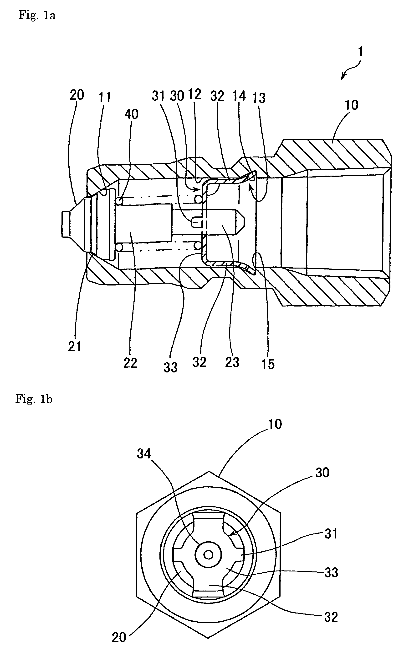
[0033]FIG. 1a is a sectional view of a male coupling 1 equipped with a sheet metal valve holding member according to one embodiment of the present invention. FIG. 1b is a right side view of FIG. 1a.

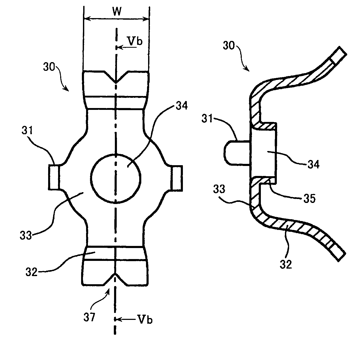
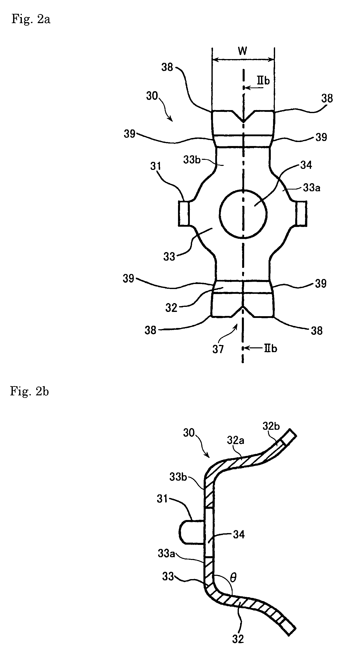
[0034]In use of the male coupling 1, a pipe (not shown) is connected to the right side of a coupling body 10 as seen in FIG. 1a, while a female coupling (not shown) is connected to the left side of the coupling body 10. The annular coupling body 10 is provided with a poppet valve 20, a coil spring 40 for biasing the poppet valve 20, and a valve holding member 30 for holding the coil spring 40 and the poppet valve 20. The valve holding member 30, as will be described later, has a hub part 33 having a guide hole 34 for slidably receiving a valve stem of the poppet valve and arm parts 32 extending from the peripheral edge of the hub part.

[0035]In assembly of the ...


PUM


Abstract

There is provided a valve holding member for holding a valve of a pipe coupling. The valve holding member includes a hub part 33 having a guide hole 34 for a valve stem, two arm parts 32 diametrically opposing each other on the peripheral edge of the hub part, and spring holding parts 31 formed at the peripheral edge.

Description

[0001]This application is a continuation of PCT / JP2005 / 020322, filed Nov. 4, 2005, which claims priority to Japanese Application No. JP2004-324974 filed Nov. 9, 2004. The entire contents of these applications are incorporated herein by reference.BACKGROUND OF THE INVENTION[0002]1. Field of the Invention[0003]The present invention relates to a valve holding member for holding a valve for opening and closing a fluid passage of a pipe coupling and, more particularly, to a valve holding member made of a single sheet metal.[0004]2. Description of the Related Arts:[0005]In a pipe coupling which employs a poppet valve for opening and closing a fluid passage, a valve holding member is used which has a hub part through which a valve stem extends, and a plurality of arm parts extending radially outwardly from the peripheral edge of the hub part and securely engaging with the inner surface of the fluid passage to retain the hub part in the center of the fluid passage. The valve is set such tha...

Claims


Application Information

Patent Timeline
Patent Type & Authority Patents(United States)
IPC IPC(8): F16K51/00F16L29/00F16L37/28
CPCB60G17/0528B60G2500/204F16F1/12F16L37/30
Inventor NISHIO, TAKUYAYAMASHITA, JINSANADA, HIDEYUKI
Owner NITTO KOHKI CO LTD
Why Eureka
Try Eureka