Exhaust fan

a technology of exhaust fan and fan body, which is applied in the direction of liquid fuel engines, machines/engines, stators, etc., can solve the problems of mold spore accumulation, door warpage, paint peeling,

Inactive Publication Date: 2009-01-06
INTELLIGENT HOME PRODS
View PDF14 Cites 51 Cited by
  • Summary
  • Abstract
  • Description
  • Claims
  • Application Information

AI Technical Summary

Problems solved by technology

The moisture can cause paint to peel, doors to warp and the accumulation of mold spores.
However, there are several drawbacks to utilizing a metal enclosure such as excessive noise, heat dissipation, heat retention, inefficient air flow, etc.

Method used


Image

  • Exhaust fan
  • Exhaust fan
  • Exhaust fan

Examples


Embodiment Construction

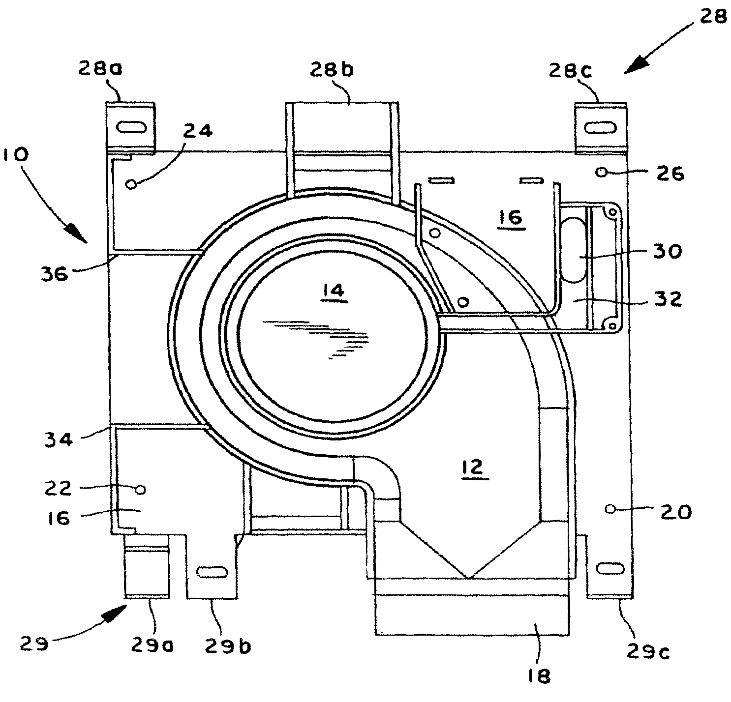
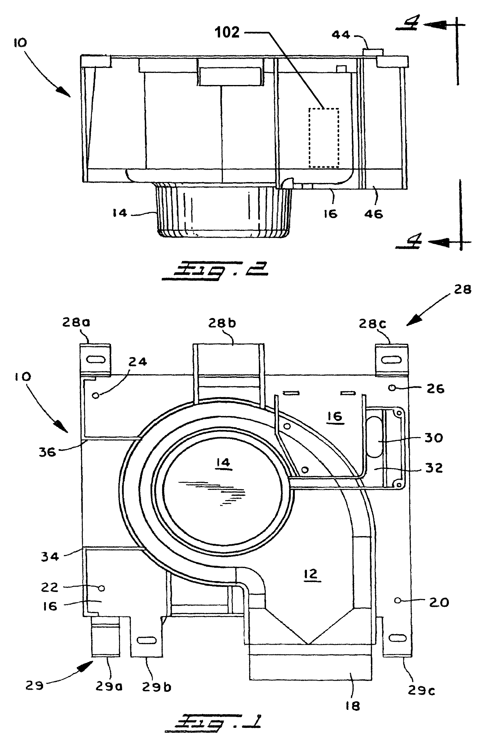
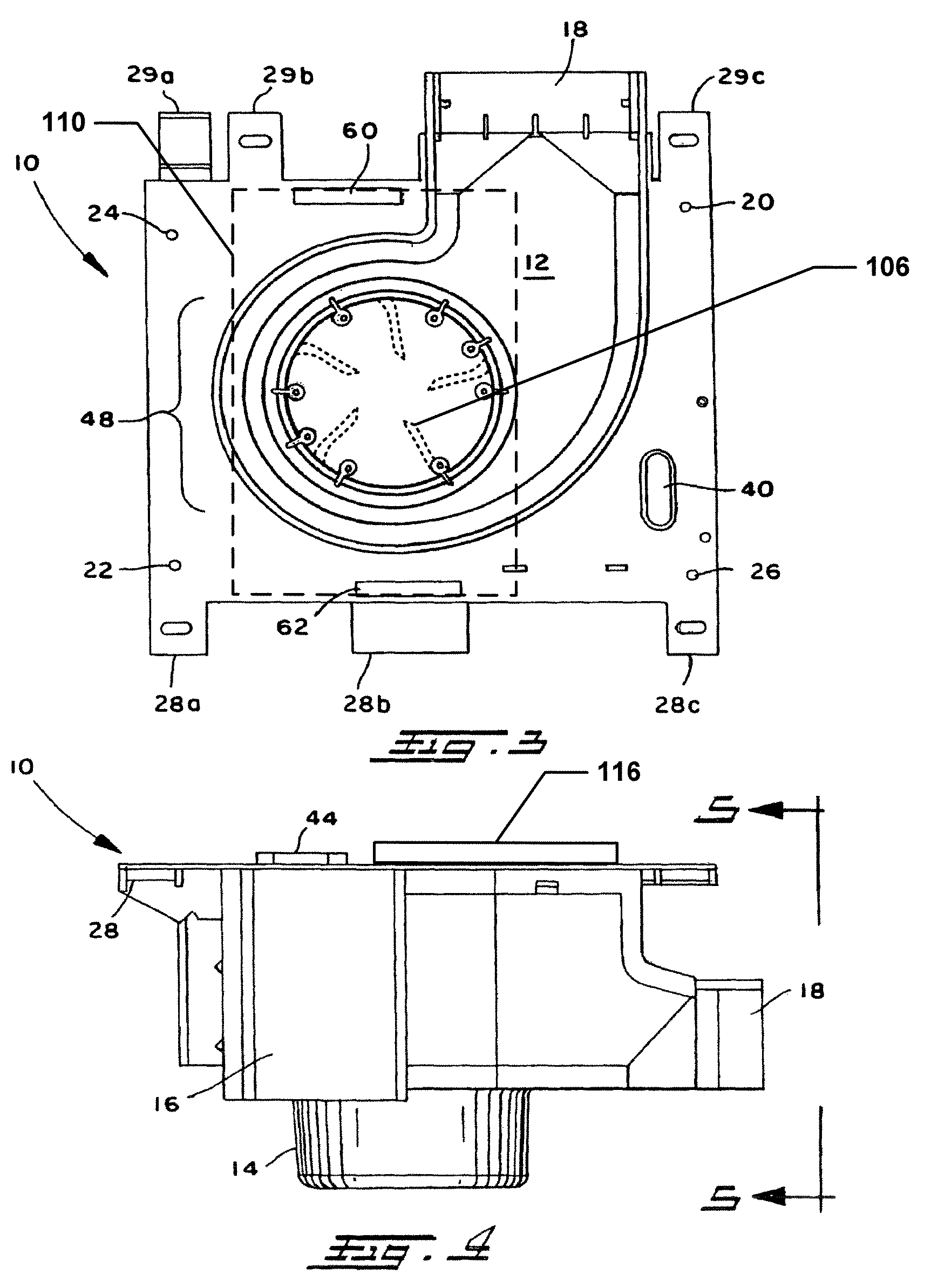
[0017]FIG. 1 illustrates a top view of a fan housing 10, which can be comprised of substantially the same material throughout. The fan housing 10 includes a flow path 12, an impeller housing 14, and an electrical enclosure 16. The impeller housing 14 can house an impeller (not shown) that draws air from a space into the flow path 12 and expels this air through an exhaust port 18. As shown, the flow path 12 is located circumferentially around the impeller housing 14. Mounting holes 20, 22, 24, and 26 can be employed to mount the fan housing 10 to one or more structures.

[0018]The fan housing 10 can be constructed of a phenolic, a thermoplastic, a thermoset, an elastomer, a plastic, a resin, etc. In one example, the fan housing 10 is constructed of a two-stage injection molded mineral filled phenolic. Such material can conform to any number of suitable standards promulgated by one or more standardizing bodies (e.g., UL, ASTM, ANSI, etc.). In another example, the fan housing 10 is const...


PUM


Abstract

The subject invention relates to a fan housing, comprising a unitary molded structure formed from a material that has a flame spread rating of twenty five or less. The unitary molded structure comprises a base, an impeller housing centrally located next to the base, and a flow path located circumferentially around the impeller housing with one or more defined walls for directing air flow. An exhaust port receives air from the flow path and outputs air in a particular direction.

Description

BACKGROUND[0001]Unwanted moisture, stale air, odors, etc. can accumulate within enclosed spaces. In one example, moisture from steam can accumulate within a bathroom. The moisture can cause paint to peel, doors to warp and the accumulation of mold spores. A simple exhaust fan can greatly reduce or eliminate various problems created by excess moisture. In such cases, a ventilation device such as an exhaust fan can be employed to draw air containing unwanted moisture, odors, etc. out of the enclosed space and expelled into another area such as the surrounding atmosphere.[0002]Ventilation devices have been available for many years. Many of these products are recessed in a ceiling and connected to a duct leading to the exterior of a home or other structure. A basic ventilation device includes an electrical enclosure and a fan driven by an electric motor. Typically, the device is switched so that a user may energize the motor, causing the fan to draw air through a grill and the air via a...

Claims


Application Information

Patent Timeline
Patent Type & Authority Patents(United States)
IPC IPC(8): F04D29/44
CPCF04D29/023F04D29/4226F05D2300/43
Inventor HERBST, WALTERHAND, JAMES C.
Owner INTELLIGENT HOME PRODS
Why Eureka
Try Eureka