Electrical connector

a technology of electrical connectors and connectors, applied in the direction of coupling device connections, fixed connections, coupling protective earth/shielding arrangements, etc., can solve the problems of affecting the emi effect, how to control the impedance to the desired value, leakage of noise, etc., to improve the emi effect and improve the conductive shell

Inactive Publication Date: 2009-01-06
HON HAI PRECISION IND CO LTD
View PDF16 Cites 17 Cited by
  • Summary
  • Abstract
  • Description
  • Claims
  • Application Information

AI Technical Summary

Benefits of technology

[0005]Accordingly, an object of the present invention is to provide an ele

Problems solved by technology

However, it is right the cutouts cause the leakage of noises which affects the EMI effect.
Th

Method used


Image

  • Electrical connector
  • Electrical connector
  • Electrical connector

Examples


Embodiment Construction

[0015]Reference will now be made to the drawing figures to describe the present invention in detail.

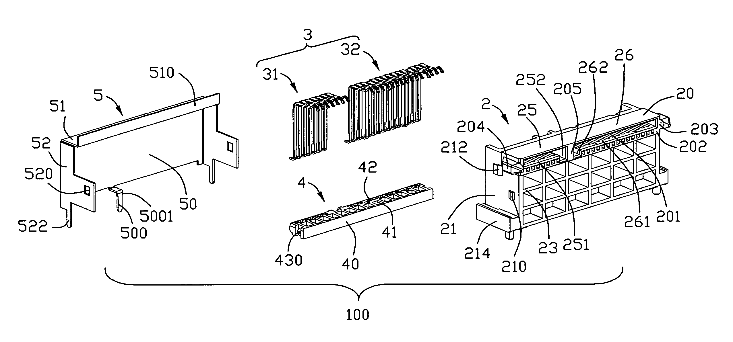
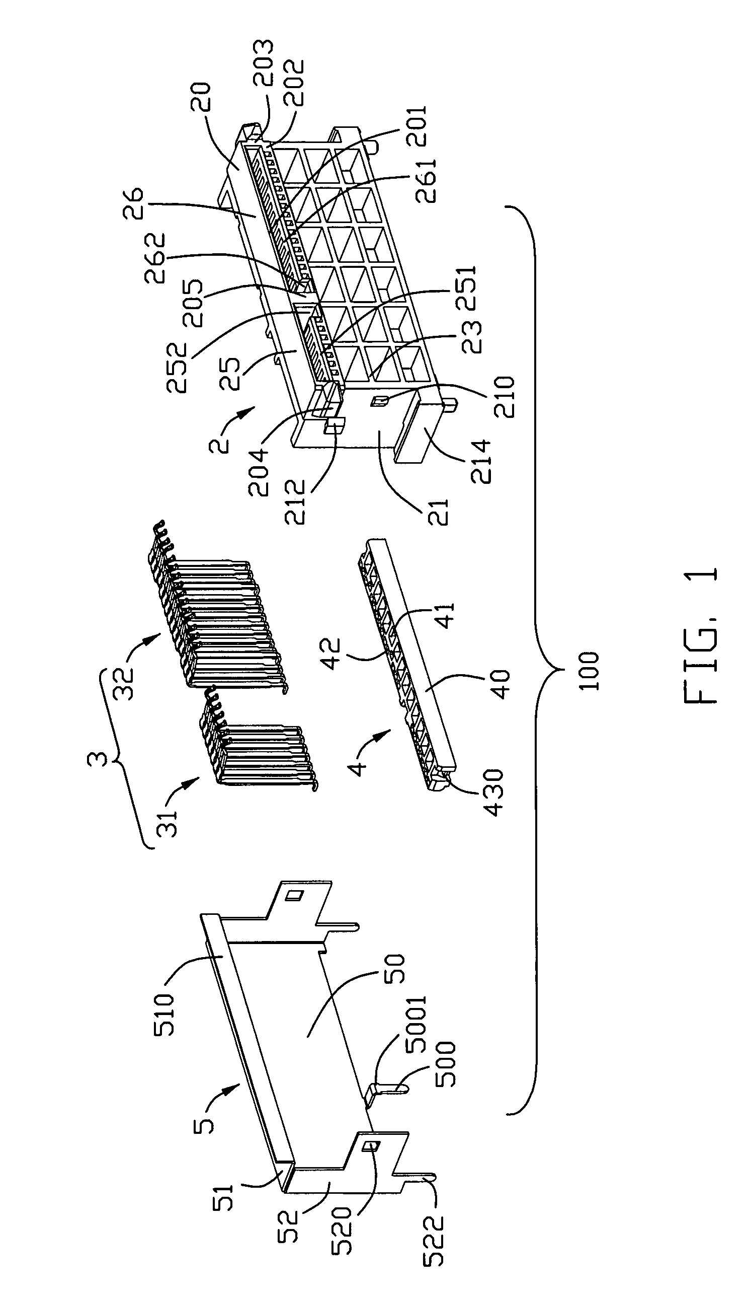
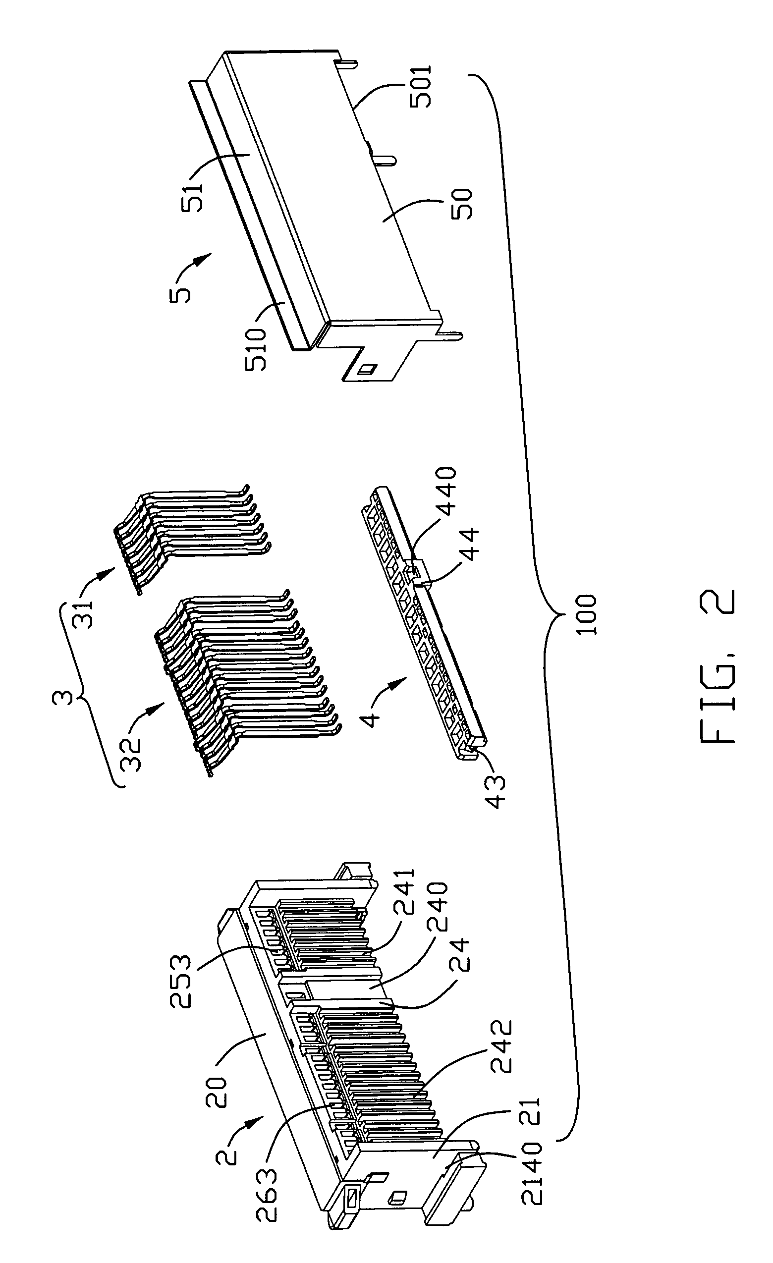
[0016]Please refer to FIGS. 1-3, an electrical connector 100 in accordance with the present invention comprises an insulative housing 2, a plurality of contacts 3 accommodated in the insulative housing 2, a spacer 4 assembled to the insulative housing 2 and aligning the contacts 3, and a conductive shell 5 assembled to the insulative housing 2 and the spacer 4 to shield the contacts 2.

[0017]Still to FIGS. 1-3, the insulative housing 2 comprises a mating port 20, a pair of L-shape sidewalls 21 extending downwardly and rearwardly from outmost edges of the mating port 20, a rear wall 24 formed between the pair of sidewalls 21 and connecting with the rear end of the mating port 20, and a front wall opposite to the back wall. The mating port 20 comprises an upper wall 201, a lower wall 202 opposite to the upper wall 201, and a pair of lateral walls 203 connecting with the upper and lower w...


PUM


Abstract

An electrical connector (100) includes an insulative housing (2), a number of first and second contacts (31, 32) accommodated in the insulative housing and a conductive shell (5). The insulative housing includes first and second mating segments (25, 26) side by side arranged along a lateral direction perpendicular to a mating direction and divided by a partition wall (205), and a rear wall (24) extending downwardly from rear ends of the first and second mating segments and forming a division section to divide the rear wall into two parts corresponding to the first and second mating segments. The first and second contacts are received in the insulative housing with mating portions (30) thereof received in the first and second mating segments, and leg portions (34) bending downwardly to be located in the two parts of the rear wall. The conductive shell encloses the insulative housing and the contacts except the first and second mating segments and mating portions of the contacts. The conductive shell forms a solder foot (500) aligning with the division section of the rear wall of the insulative housing for being assembled to a printed circuit board.

Description

BACKGROUND OF THE INVENTION[0001]1. Field of the Invention[0002]The present invention generally relates to an electrical connector, and more particularly to an electrical connector used for high-speed transmission.[0003]2. Description of Related Art[0004]Impedance match and EMI issue are two most important things for signal transmission of electrical connectors. Different kinds of ways are adopted by designers to adjust the impedance of contacts to proper value and improve the EMI effect. To adjust the impedance of contacts to proper value, designers usually adopt the way of changing the dielectric constant around the contacts. To improve the EMI effect, designers usually adopt a conductive shell to cover housing and contacts to depress EMI. These solutions are more important for connectors used in external circumstances. As disclosed by U.S. Pat. Nos. 7,052,321 and 6,758,685, conductive shells are adopted to enclose housings and contacts to improve EMI effect. Particularly, rear wa...

Claims


Application Information

Patent Timeline
IPC IPC(8): H01R13/648H01R12/55
CPCH01R13/2442H01R12/707H01R12/712H01R13/6594H01R13/6473
Inventor ZHANG, GEORGEHUANYI
Owner HON HAI PRECISION IND CO LTD
Why Eureka
Try Eureka