Method and apparatus for grinding a workpiece

Active Publication Date: 2009-01-06
OPTOMEC INC
View PDF9 Cites 15 Cited by
  • Summary
  • Abstract
  • Description
  • Claims
  • Application Information

AI Technical Summary

Benefits of technology

[0010]Accordingly, a need exists for properly forming profiles in a turbine disk or related workpiece using a method and apparatus that avoids many of the disadvantages of the curren

Problems solved by technology

As a result, broaching machines are very expensive, very heavy so as to require special foundations, and involve a significant amount of time to reset the cutting members for each new job.
Also, the cutting teeth require frequent resharpening.
First, the purchase price, maintenance cost, floor space requirements and long lead-time to obtain broaching machines is a significant disadvantage.
Additionally, the machines must be supported on a special concrete base with other infrastructure to support broaching machines, which adds to the overall cost of the machines.
Finally, the cutting elements of the broaching machine must be resharpened frequently, and a significant amount of time is required to set up and change over broaching machines to cut profiles with different profiles.
As the grinding wheel is applied to the workpiece, the workpiece is ground away by the abrasive surface of the grinding wheel, which also generally results in very small loose particles or grits of the grinding wheel surface being separated from the grinding wheel.
The grinding action of the grinding wheel may generate sufficient heat to actually “burn” the workpiece to the point at which the microstructure and properties of the workpiece are altered that can crea

Method used


Image

  • Method and apparatus for grinding a workpiece
  • Method and apparatus for grinding a workpiece
  • Method and apparatus for grinding a workpiece

Examples


Example

[0027]As best seen in the accompanying drawings, the present invention provides a method and apparatus for forming the profiles in a turbine disk or similar workpiece utilizing a unique grinding system.

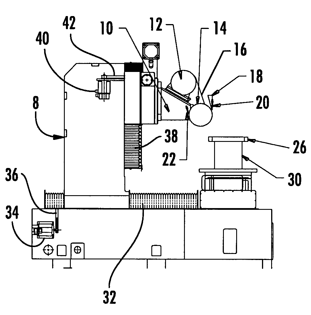
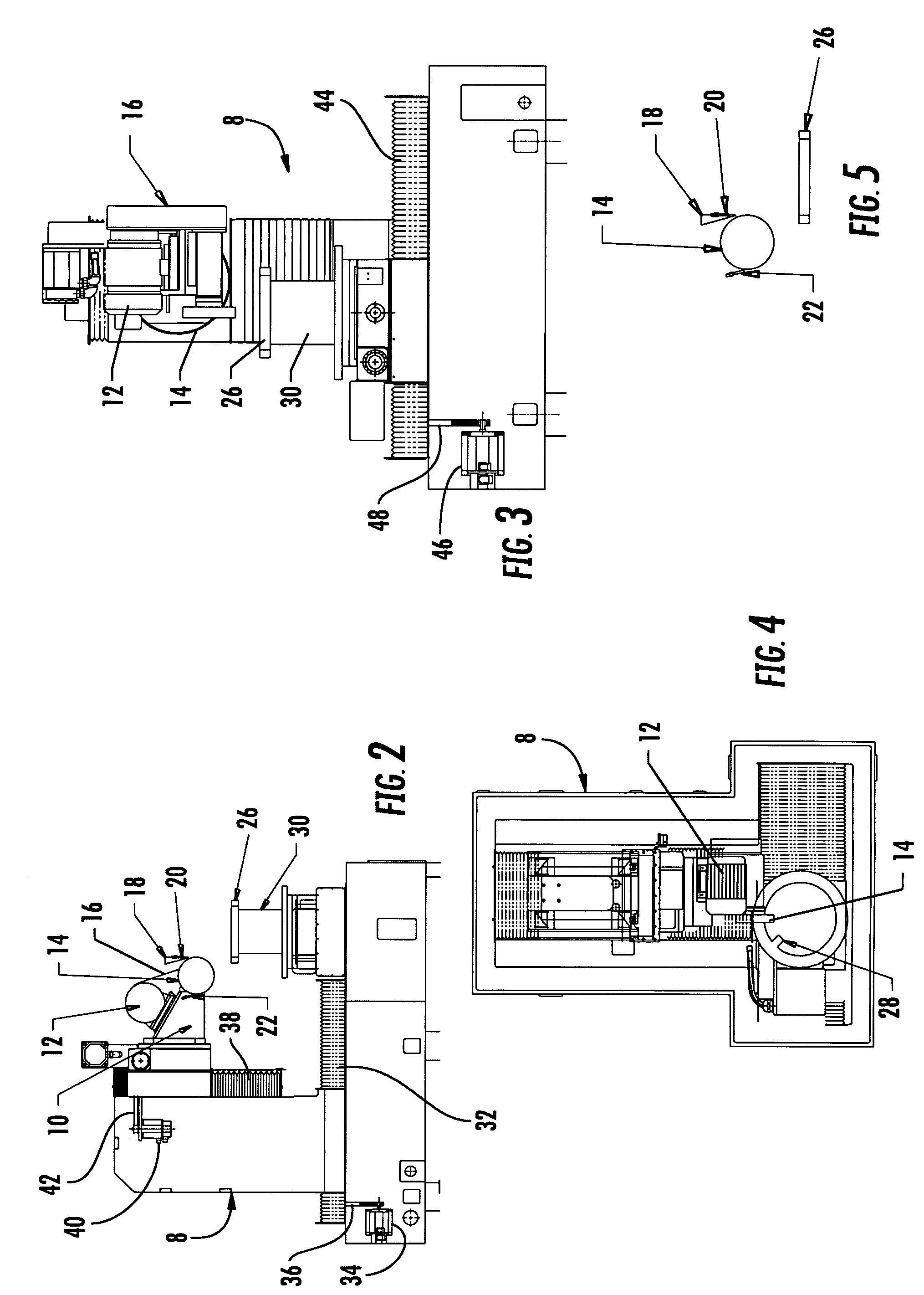
[0028]More specifically, as best seen in FIGS. 2-4, the grinding apparatus 8 of the present invention includes a support 10 on which is mounted a drive motor 12, and a grinding wheel 14 that is rotated by the drive motor 12 through a drive belt system 16 or other suitable drive means. The system also includes a plurality of coolant delivery nozzles which are diagrammatically illustrated in FIG. 5, including a primary nozzle 18, a corner nozzle 20, and a scrubber nozzle 22, all of which are constructed and arranged to provide a pressurized flow of coolant directly to the surface of the grinding wheel 14, with low aeration. Finally, a conventional computerized monitoring system 24 is provided for monitoring the flow of coolant through the nozzles 18-22, and the monitoring system 24 can ...


PUM

PropertyMeasurementUnit
Temperatureaaaaaaaaaa
Pressureaaaaaaaaaa
Flow rateaaaaaaaaaa

Abstract

A method and apparatus for cutting a profile in a workpiece, such as a turbine disk, without cracking the parent material which includes providing a grinding wheel having a ceramic grinding surface formed with an optimized grain material and grain spacing to produce large chips that are easily removed from the workpiece, applying the grinding wheel to the workpiece at a predetermined material removal rate, and increasing the material removal rate when the burning point is recognized at the surface of the workpiece by the grinding action of the grinding wheel, and delivering coolant/lubricant to the workpiece during the grinding operation.

Description

CROSS-REFERENCE TO RELATED APPLICATION[0001]This application is entitled to the benefit of, and claims priority to, provisional U.S. Patent Application Ser. No. 60 / 836,518 filed Aug. 9, 2006, and entitled “METHOD AND APPARATUS FOR GRINDING A WORKPIECE,” the entirety of which is incorporated herein by reference.BACKGROUND OF THE PRESENT INVENTION[0002]This invention relates generally to an apparatus and method for grinding a workpiece, and more particularly to the grinding of the base portion of turbine and compressor disks or rotors (which are hereafter collectively referred to as “turbine disks”) and related types of workpieces.[0003]The base or root portions of turbine blades are generally formed with a series of shoulders which are closely fitted into profiles of the corresponding support portions of the turbine disks to make sure that the turbine blades are maintained securely in place during rotation of the disks.[0004]Heretofore, the desired configuration of the profiles in th...

Claims


Application Information

Patent Timeline
IPC IPC(8): B24B49/00
CPCB24B19/009B24B49/14B24B55/02
Inventor GERSTNER, DANIEL THOMAS
Owner OPTOMEC INC
Why Eureka
Try Eureka