
Molded spreader disk

a spreader disk and molded technology, applied in baling, agriculture, agricultural tools and machines, etc., can solve the problems of affecting the effectiveness of agricultural chemicals, difficult for crops to utilize nutrients, and detrimental temperature and moisture gradients, so as to facilitate the rearward flow and distribution of crop residues, and reduce the effect of side-to-side distribution

Inactive Publication Date: 2009-01-06
BLUE LEAF I P INC
View PDF22 Cites 22 Cited by
  • Summary
  • Abstract
  • Description
  • Claims
  • Application Information

AI Technical Summary

Benefits of technology

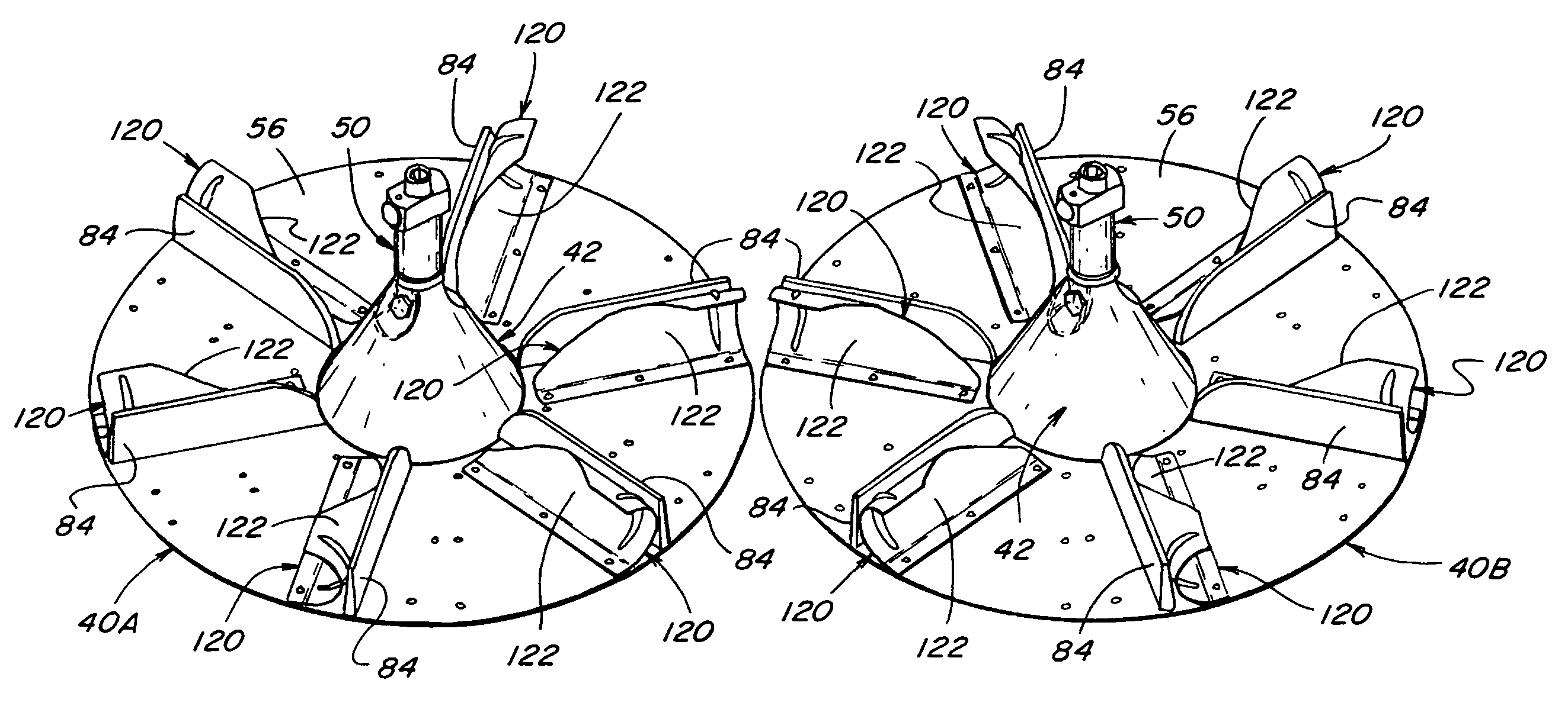
[0008]The present invention offers users a cost effective alternative, in terms of both parts costs and time savings, to the known spreader disk assemblies that have included separate spreader cones, spreader plates, and spreader bats, and which have required the investment of user time for configuration and assembly for use, while preserving much of the versatility that could be realized with the pre-existing disk assemblies. In its more basic form, the invention comprises a construction formed or molded as a unitary member that can replace or be employed in lieu of the sundry separate components that were previously required to assemble and use a spreader disk assembly, which construction incorporates into a unitary member at least a spreader plate and associated integral spreader blades or blade elements, and in further optional configurations, a spreader cone or a spreader cone with an associated conical linkage.
[0017]Optionally, additional separately installable spreader bats can also be employed with the molded spreader bat disks. To accommodate the additional separately installable spreader bats, the spreader bat disks may include mounting holes at various locations, and such additional spreader bats, which may be of various configurations, can be securably attached to the spreader bat disks, such as by attaching them to the spreader bat disks at the locations of various mounting holes in either the web portion or along the integral spreader blades. One preferred form of additional spreader bats includes a concave blade which can be installed generally adjacent an integral spreader blade on the spreader bat disks, on either side of the integral spreader blade, depending upon the left and right mounting configuration of the spreader bat disk, for either aggressive or retarded throw positioning. Additional mounting holes in the spreader bat disk can also accommodate the installation of the additional spreader bats at middle or neutral positions between the integral spreader blades.
[0019]Such spreader bat disks can also be employed during windrowing operations, especially when the bottom surface of the web portion is essentially flat, to facilitate the rearward flow and distribution of the crop residue behind the combine without undesired spreading across the swath of the crop cut by installing the spreader bat disks upside down relative to the spreader cones. In such instances, the top surfaces of the spreader bat disks and the integral spreader blades projecting therefrom will face downwardly, towards the ground surface, and the generally flat and smooth bottom surfaces of the spreader bat disks will face upwardly towards the crop residue output port and the crop residue being discharged therefrom. The counter-rotating action of the spreader bat disks, when so installed upside down, will tend, due to the relatively smooth bottom surfaces of the spreader bat disks and the lack of spreader bats thereon, to propel the crop residue rearwardly with minimal sidewardly distribution.
[0020]Increased cost savings can be further realized by also incorporating the spreader cone with the spreader bat disk into a unitary construction, hereinafter referred to as a spreader cone disk, and still further cost savings can then be realized by further incorporating the conical linkage with such spreader cone disk into a unitary construction, referred to hereinafter as an integral spreader head.

Problems solved by technology

Included among such reasons are that uneven crop residue distribution on a field can lead to temperature and moisture gradients detrimental to even growth of future crops on the field, uneven distribution can make it difficult for crops to utilize nutrients, and uneven distribution can impact the effectiveness of agricultural chemicals.
In addition, the existence of large discontinuities of spread crop residue can lead to plugging and other functional problems when such discontinuities are encountered by tillage and / or planting equipment.
The versatility of such spreader assemblies, however, is tempered by the associated costs of the assemblies and their multiple configurable parts, taking into account not only the materials of such spreader assemblies, but also the varying configurations and quantities of individual components required, as well as the time required for assembly and disassembly.

Method used


Image

  • Molded spreader disk
  • Molded spreader disk
  • Molded spreader disk

Examples


Embodiment Construction

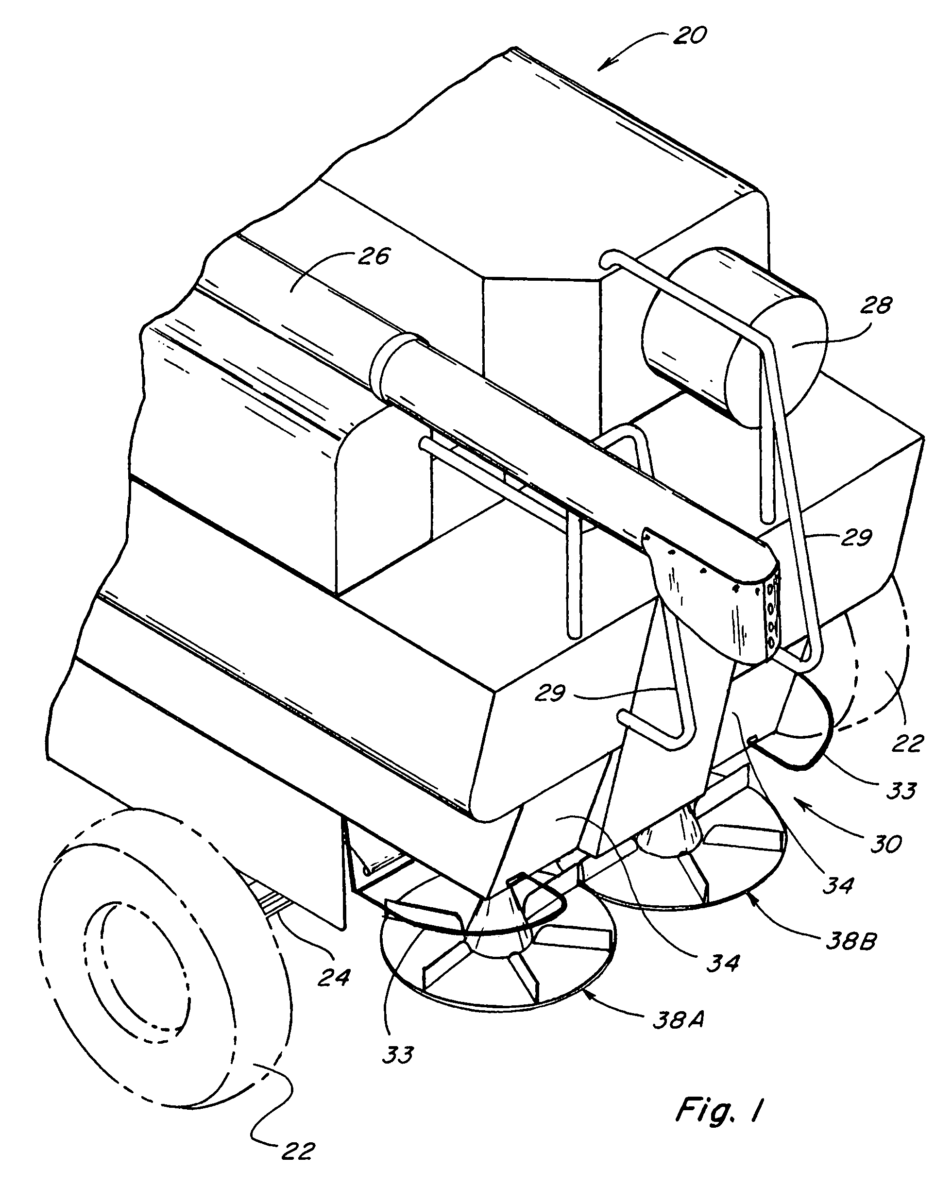
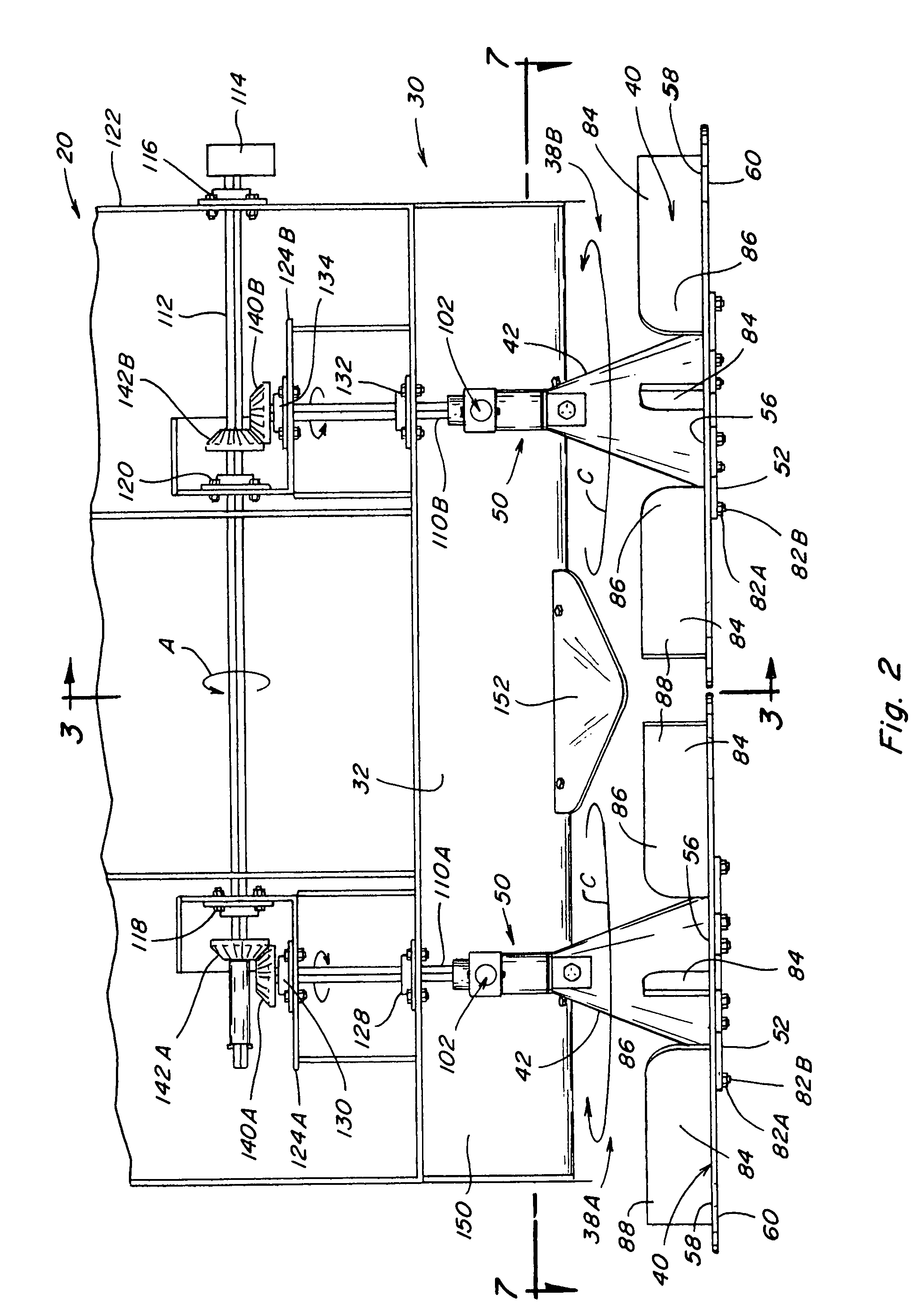
[0034]Referring now to the drawings, wherein like numerals refer to generally like items and wherein certain numerals are applied on a representational basis to selected, representative items of a class of like items instead of to all of the depicted like items, FIG. 1 depicts the rear portion of a typical combine 20 having a pair of rear tires 22 mounted upon a rear axle 24, with a grain auger or threshing rotor 26, an engine radiator air screen 28, and handrails 29 mounted upon the upper structure of the combine 20. A spreader assembly 30, as better shown in FIGS. 2 and 3, is mounted generally below a crop residue discharge chute 32 (FIG. 3). For safety and other purposes, guard bars 33 (FIG. 1) are mounted extending generally over and across certain more exposed portions of the spreader assembly 30 and removable drive linkage cover plates 34 enclose associated drive linkages. When the threshing rotor 26 is operating, crop residue from such operation is discharged into discharge c...


PUM


Abstract

A spreader bat disk for a spreader assembly that has a drive linkage operable to rotatably drive attachments thereto, the spreader bat disk being formed or molded as a unitary construction that includes a web portion, preferably of a generally circular configuration, having a top surface and an essentially flat bottom surface, with a plurality of integral radially distributed spreader blades projecting upwardly from the top surface, and which is configured to be operatively connectable to the drive linkage of the spreader assembly to be rotated thereby to spread material provided thereto.

Description

TECHNICAL FIELD[0001]This invention relates to mechanisms adapted for spreading material, particularly crop residue that is discharged from the rear output port of a harvester combine, and especially to mechanisms that have utilized dual spinning circular crop residue spreader disk assemblies assembled from separate spreader plates and associated spreader bats, and, more particularly, to the spreader disk assemblies of such mechanisms.BACKGROUND ART[0002]Typically, as a harvester combine moves forward through a crop such as wheat, the wheat is cut and conveyed upwardly into the combine and into a threshing portion thereof where the grain is separated from the wheat stalks and then conveyed by the combine to a series of sieves where the chaff is blown away from the grain by blasts of air. The grain separated from the chaff is conveyed within the combine to a grain chute, while the crop residue, including the straw stalks and chaff, is typically conveyed or blown rearwardly to be disc...

Claims


Application Information

Patent Timeline
Patent Type & Authority Patents(United States)
IPC IPC(8): A01F12/30
CPCA01D41/1243
Inventor SCHWINN, KEVIN S.MURRAY, CRAIG E.DOBBINS, DAVID V.
Owner BLUE LEAF I P INC
Learn More