Directional hearing given binaural hearing aid coverage

a binaural hearing aid and directional hearing technology, applied in the field of hearing aid systems, can solve the problems of different signal transit times within the hearing aid devices, loss of directional hearing, and different degree of hearing loss for hearing aid users, and achieve the effect of minimizing the additional computing expenditur

Inactive Publication Date: 2009-01-06
SIVANTOS PTE LTD
View PDF12 Cites 15 Cited by
  • Summary
  • Abstract
  • Description
  • Claims
  • Application Information

AI Technical Summary

Benefits of technology

[0016]An object of the present invention is to support natural directional hearing given a hearing aid system with binaural coverage and to minimize the additional computing outlay required.

Problems solved by technology

Further, the hearing loss for a hearing aid user is usually of a different degree in the two ears.
Different settings of the signal processing of the two hearing aids, however, usually result in different signal transit times within the hearing aid devices.
Even slight changes of this natural transit time shift as caused, for example, by different signal transit times within the hearing aid devices, can therefore lead to a loss of directional hearing.
The first-cited solution has the disadvantage that a further assembly is needed and the hearing aid user now requires three devices instead of two, which means a considerable limitation of the wearing comfort, maintenance and manipulation.
Whereas adequate space is present in the solution with a third device in order to provide a correspondingly powerful signal processing, the space in a hearing aid situated at the ear is limited.
Although the transmission of the microphone signals of both sides of a binaural hearing aid system to the respectively other side and the simultaneous processing of both signals at both sides solves the problem of a transit time difference, it is subject to the same limitations as the master-slave approach.
Another significant disadvantage of all of these solutions is that they all require the transmission of large quantities of data.
This causes a substantial use of time, space and energy, and represents a considerable disadvantage, particularly given wireless data transfer as offered in the present state of the art.

Method used


Image

  • Directional hearing given binaural hearing aid coverage
  • Directional hearing given binaural hearing aid coverage
  • Directional hearing given binaural hearing aid coverage

Examples


Embodiment Construction

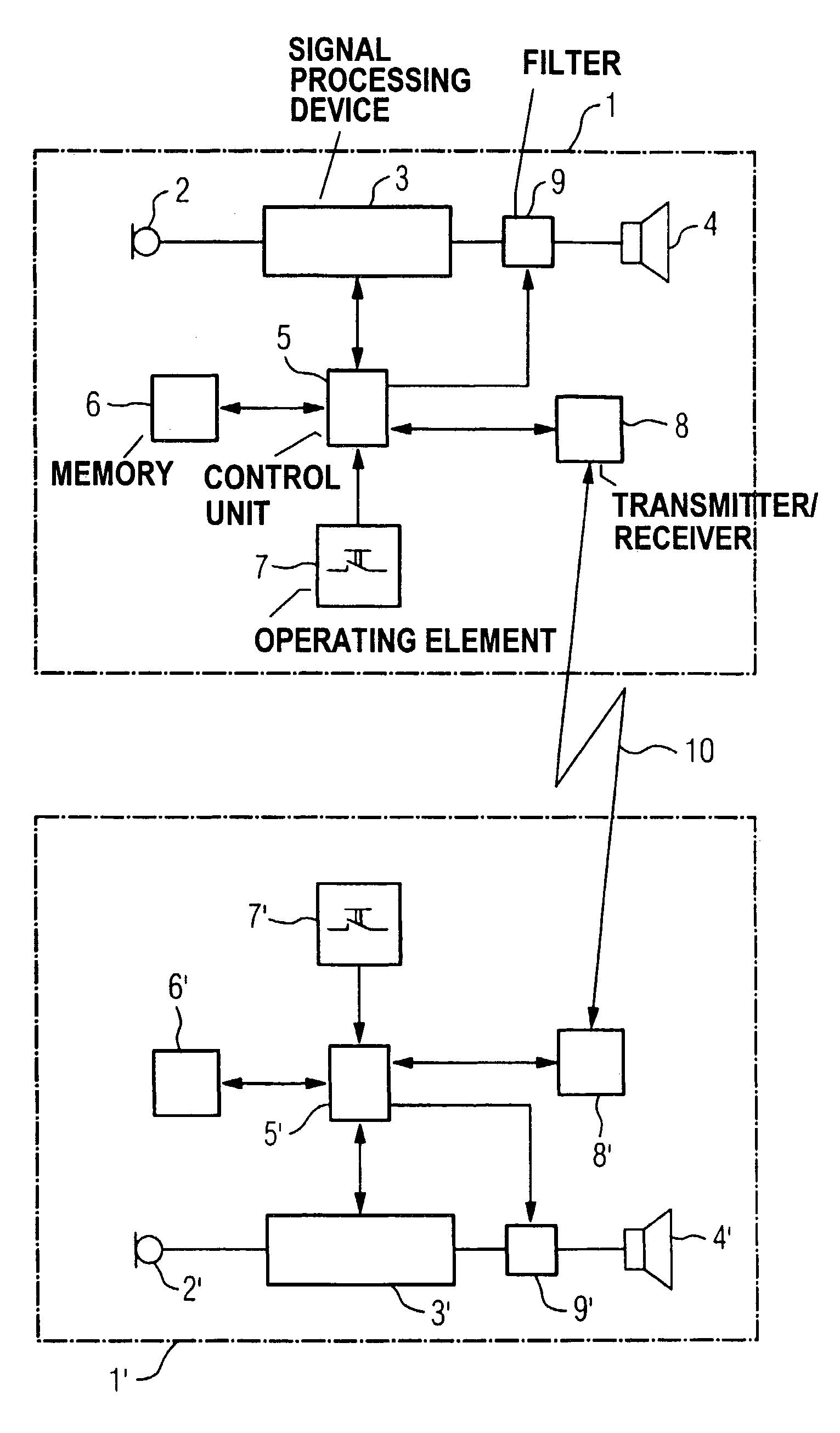
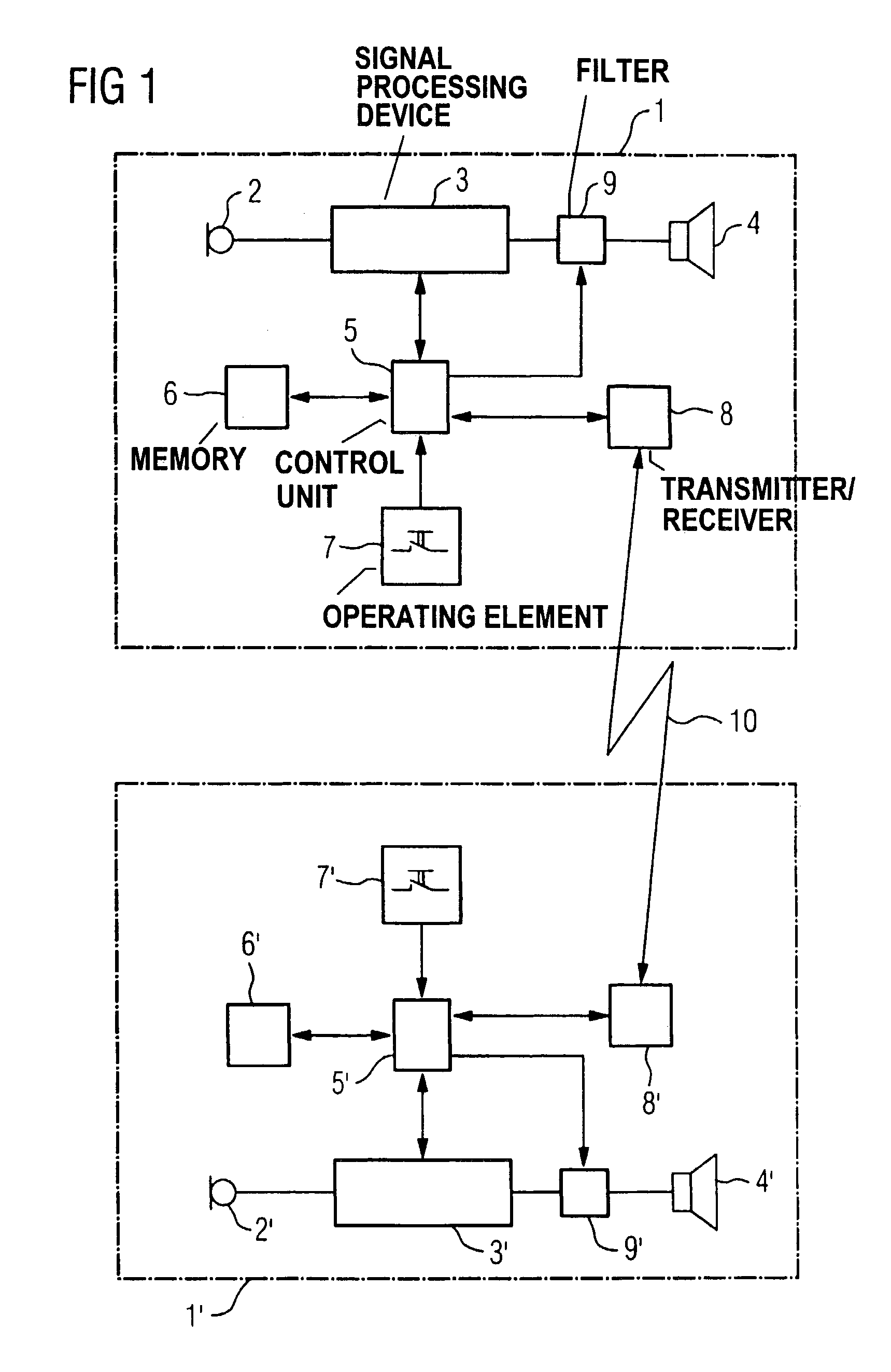
[0027]Given a hearing aid system with two hearing aids as known from the initially cited Prior Art, an identical signal transit time in the signal paths of the two hearing aid devices between the microphone and the earphone is respectively generated without explicitly knowing this signal transit time. The high computing outlay and the high data transmission rate that is required as disadvantageous.

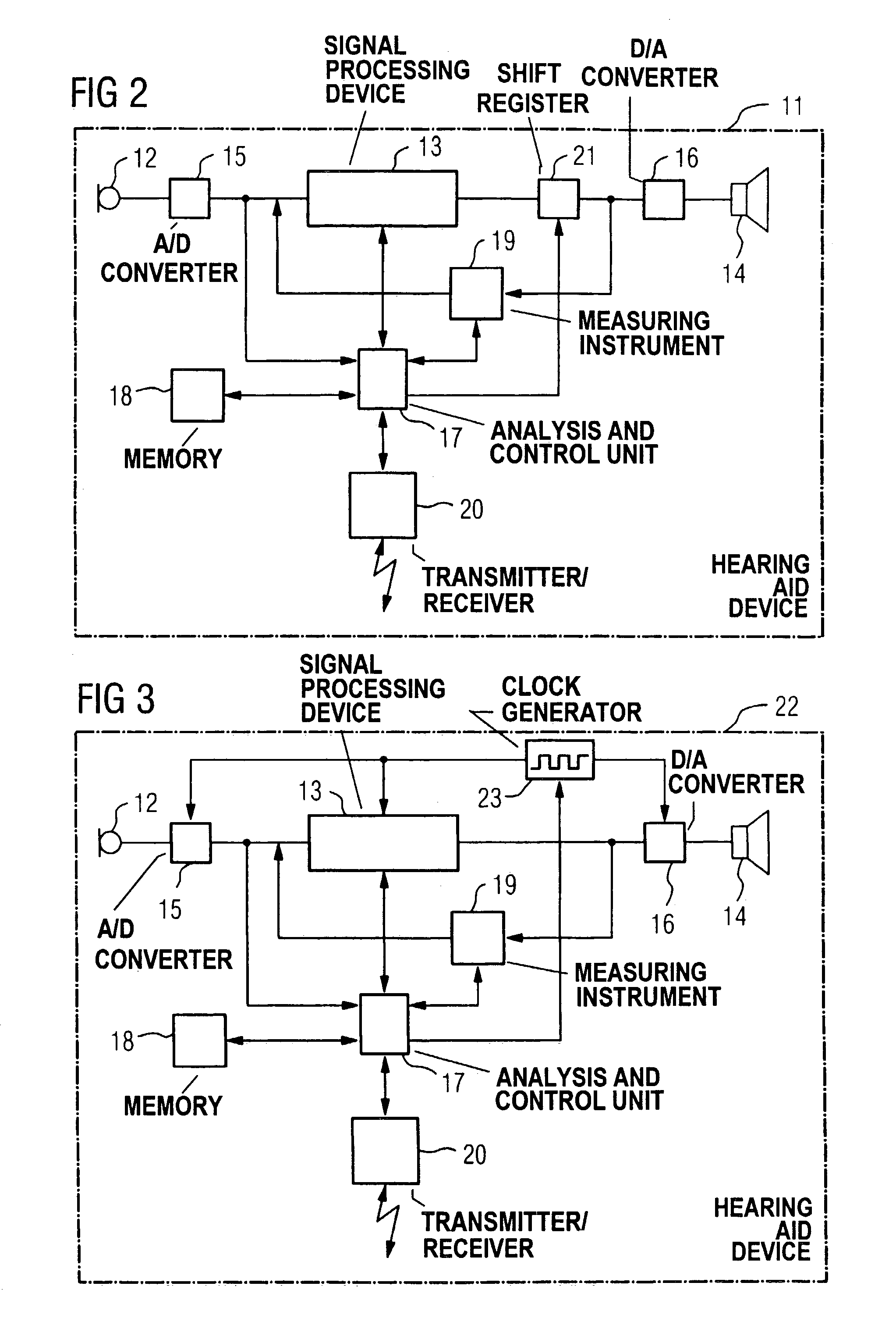
[0028]In contrast, an embodiment of the invention provides that the signal transit time of the electrical signal in the signal path between the input transducer and the output transducer of the first hearing aid device be determined at least in a relevant sub-region wherein transit time differences may be fundamentally expected, and that the signal transit time of the electrical signal between the input transducer and the output transducer of the second hearing aid device be adapted to the identified signal transit time of the first hearing aid device.

[0029]Transit time differences between...


PUM


Abstract

Directional hearing is improved given the binaural coverage for a hearing aid user with two hearing aid devices wearable at the ears. The respective signal transit times and / or signal amplitudes and / or amplifications of an electrical signal are respectively measured in a signal path between an input transducer and an output transducer and that data with respect to the measured signal transit times and / or signal amplitudes and / or gains is transmitted onto the respectively other hearing aid device. As a result, the signal transit times and the signal amplitudes of the electrical signals through the two hearing aid devices can be matched to one another. The hearing aid devices thus cause no phase or amplitude distortion, and the natural phase shift as well as the natural amplitude difference of a sound signal incident from a specific direction are thus preserved. The directional information is thus also preserved for the hearing aid user.

Description

BACKGROUND OF THE INVENTION[0001]1. Field of the Invention[0002]The invention is directed to a hearing aid system as well as to a method for the setting of a hearing aid system having at least a first and a second hearing aid device that at least respectively comprise at least one input transducer for the pick-up of an acoustic input signal and conversion thereof into an electrical signal, a signal processing unit for processing the electrical signal and an output transducer for converting the electrical signal into an output signal, and between which a signal path for data transmission is provided.[0003]2. Description of the Related Art[0004]Directional hearing is the ability of a person to distinguish the direction in which a sound source is located. When a sound source is not frontally located in front of or behind the person, a difference in transit time between the two ears and, thus, a time difference with which the ears perceive a sound wave coming from a direction necessaril...

Claims


Application Information

Patent Timeline
Patent Type & Authority Patents(United States)
IPC IPC(8): H04R25/00
CPCH04R25/552
Inventor BECK, FRANKSPORER, GERHARD
Owner SIVANTOS PTE LTD
Why Eureka
Try Eureka