
Multi-axis spindle head

a spindle head and multi-axis technology, applied in the direction of machine supports, manufacturing tools, gearing, etc., can solve the problems of compactness, compactness, accuracy, rigidity,

Inactive Publication Date: 2009-01-13
SHINNIPPON KOKI
View PDF34 Cites 31 Cited by
  • Summary
  • Abstract
  • Description
  • Claims
  • Application Information

AI Technical Summary

Benefits of technology

"The present invention provides a new way to articulate a spindle head that overcomes the drawbacks of known spindle heads. The invention uses a multi-axis spindle head design that allows for additional degrees of movement in two directions. The invention also avoids the use of traditional geared rotary stages, reducing complexity and cost. The invention includes a powered mechanism and a mounting ring to articulate the spindle head about two tilt axes. The invention provides a new means to articulate a spindle head that is more efficient and has greater movement."

Problems solved by technology

Many solutions to this need have been proposed, however all are compromises involving accuracy, stiffness, compactness and complexity.

Method used


Image

  • Multi-axis spindle head
  • Multi-axis spindle head
  • Multi-axis spindle head

Examples


first embodiment

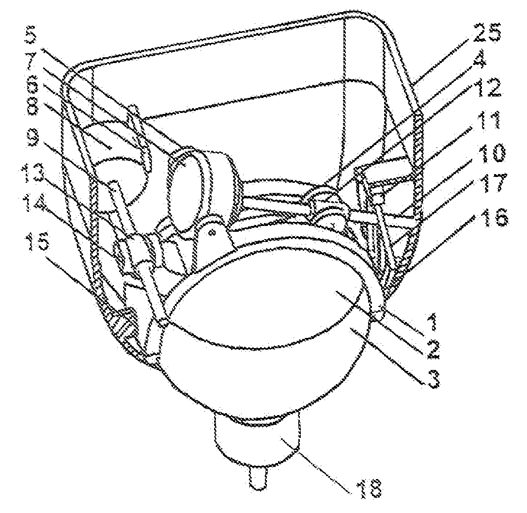
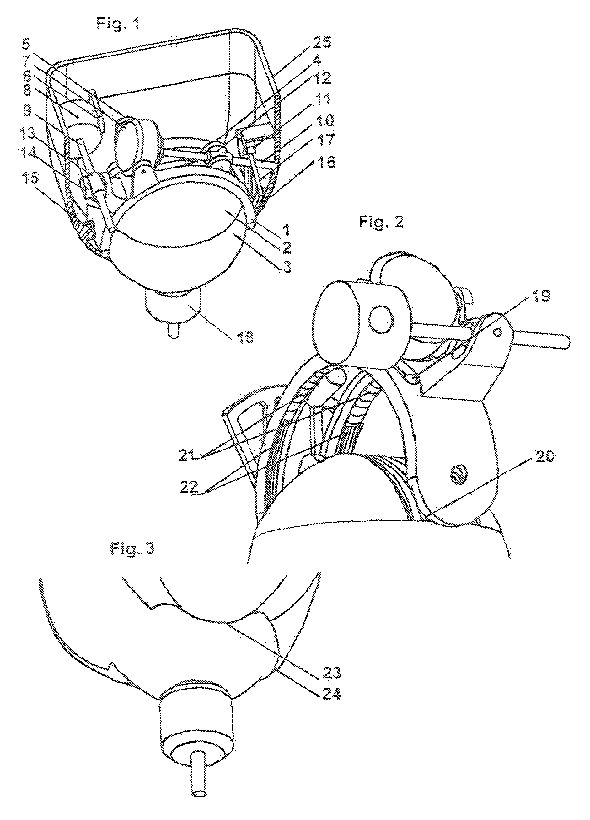
[0028]Referring to FIGS. 1 to 3 which show the invention, a rotary spindle 18 is mounted to a sphere 3 which is mounted for articulation in two orthogonal directions, a first of which is accommodated by mounting of the sphere 3 to an arcuate band 1 with the sphere being movable in one direction relative to the band by virtue of the provision of a sphere tilt motor 7 which is mounted on the band and drives the sphere. The band 1 is in turn arranged to be movable in an orthogonal direction by virtue of being pivotally mounted in a housing 25 with a band tilt motor 5 mounted in the housing and driving the band 1. The bottom of the sphere 3 is journalled a spherical socket defined in the housing 25, with the spindle 18 projecting through a window in the housing.

[0029]The band 1 is semi-circular extending to house pivot bearings 15 in its longitudinal axis. It has circumferal underside grooves 22 that act as ball bearing raceways. Conforming raceways are located in the top of the sphere ...

second embodiment

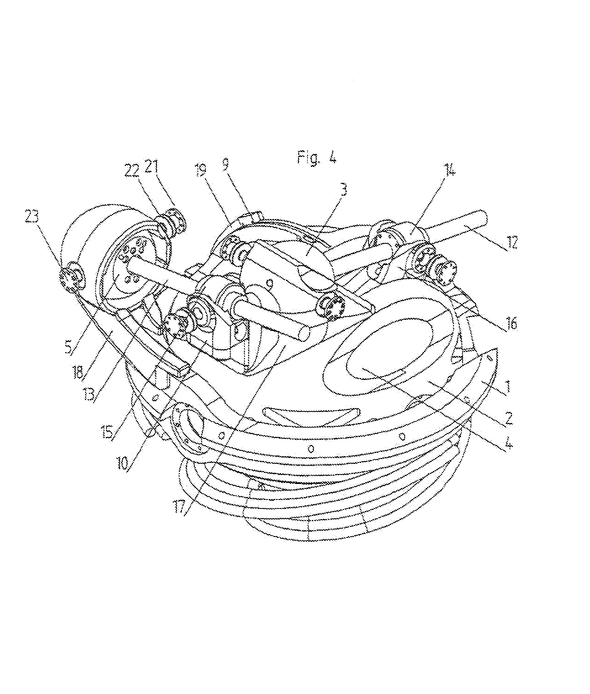
[0040]Referring now to FIGS. 4 to 8, these show the invention. In this embodiment, as will be described in detail hereinafter, a spindle unit housed in a sphere 4 is pivotally mounted in a gimbal ring 2 for tilting movement about one axis and the gimbal ring 2 is itself pivotally mounted in a mounting ring 1 for pivotal movement about an orthogonal axis. Drive motors 3 and 5 determine the movements of the sphere 4 relative to the gimbal ring 2 and of the gimbal ring 2 relative to the mounting ring 1.

[0041]As can be seen from FIGS. 4 to 8, the notional gimbal ring 2 (“notional” because though performing the function of a ring it is not in fact formed as a ring) lies orthogonal to the spindle axis C-C such that it can be pivotally supported by the mounting ring 1 about axis B-B. The gimbal ring 2 in turn supports the notionally spherical spindle unit 4 on a pivot axis orthogonal to the gimbal ring pivot axis A-A. The two orthogonal pivot axes A-A and B-B intersect at a common point th...


PUM

PropertyMeasurementUnit
degrees of freedomaaaaaaaaaa
stiffnessaaaaaaaaaa
mechanical complexityaaaaaaaaaa

Abstract

A powered mechanism able to articulate about two orthogonal tilt axes, the powered mechanism having a sphere pivotally mounted in a ring or band and driven by a first pivotally mounted motor to articulate the sphere about the first axis, and a second pivotally mounted motor mounted to a fixed reference to drive the sphere about the second axis through ring or band.

Description

FIELD OF THE INVENTION[0001]This invention relates to a powered mechanism such as a spindle head and more particularly, but not exclusively, concerns a multi-axis spindle head.BACKGROUND OF THE INVENTION[0002]With the increasing ability of designers using CAD systems to specify complex surfaces, there is a similar need for machine tools to articulate about all 5 degrees of freedom to render these surfaces in metals.[0003]Currently most machine mills move the spindle along 3 Cartesian axes, with the 2 axes tilt of the spindle not supported. It would be desirable to substitute the usual fixed axis spindle with one able to additionally tilt in 2 axes such as to upgrade 3 axis machines to 5 axes.[0004]Many solutions to this need have been proposed, however all are compromises involving accuracy, stiffness, compactness and complexity.OBJECTS AND SUMMARY OF THE INVENTION[0005]The principal object of the present invention is to overcome or at least substantially reduce some at least of the...

Claims


Application Information

Patent Timeline
Patent Type & Authority Patents(United States)
IPC IPC(8): B25J17/00B23Q5/04B23Q1/54
CPCB23Q1/5412Y10T409/308512Y10T74/19502Y10T74/20329
Inventor BAILEY, RALPH-PETER STEVEN
Owner SHINNIPPON KOKI
Learn More