Integrated heat spreader and exchanger

a heat spreader and exchanger technology, applied in the field of electronic components, can solve the problems of affecting the performance of electronic components, and the weight of the heat spreader is often too heavy to be supported, so as to reduce the thermal resistance of the interface, minimize the thickness of the interface, and reduce the heat dissipation

Inactive Publication Date: 2009-01-13
GLOBALFOUNDRIES INC
View PDF16 Cites 30 Cited by
  • Summary
  • Abstract
  • Description
  • Claims
  • Application Information

AI Technical Summary

Problems solved by technology

The heat sink having large fins and a heat spreader is often too heavy to be supported directly by the chip it is cooling, so the heat sink is attached to, and at least partially supported by, the circuit board to which the chip is attached.
The preload is generally not desirable and can be detrimental to the electronic components such as solder balls that support the chip.
More importantly, cyclic changes in the mechanical clearance between the chip and the heat spreader can result in a pumping action of TIM that can lead to voids being formed in the TIM and eventually to chip failure.
In the case of TIM materials that are not paste-like but have a viscoplastic characteristics the cyclic changes in mechanical clearance can lead to fatigue failure of a thermal interface.

Method used


Image

  • Integrated heat spreader and exchanger
  • Integrated heat spreader and exchanger
  • Integrated heat spreader and exchanger

Examples


Embodiment Construction

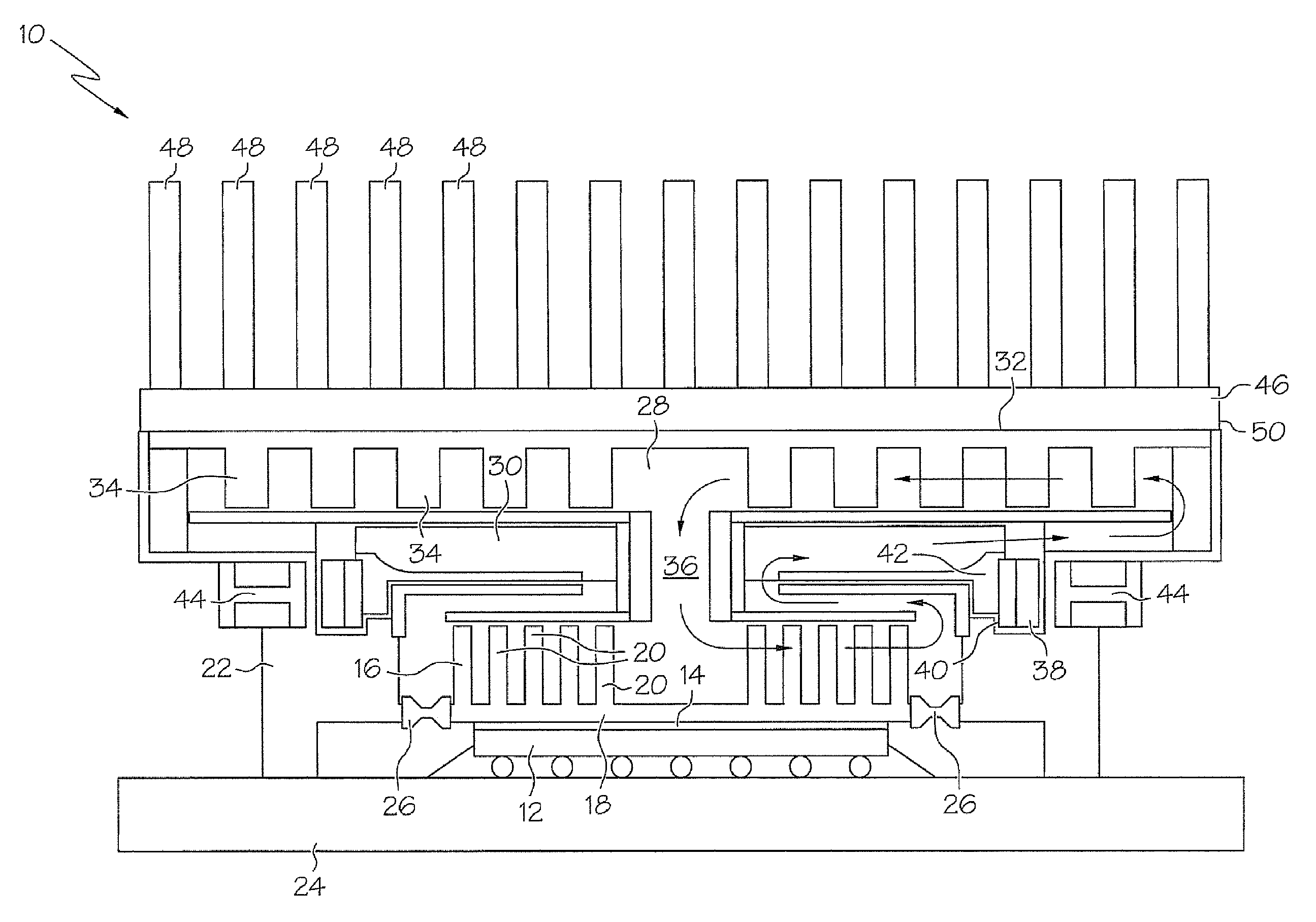
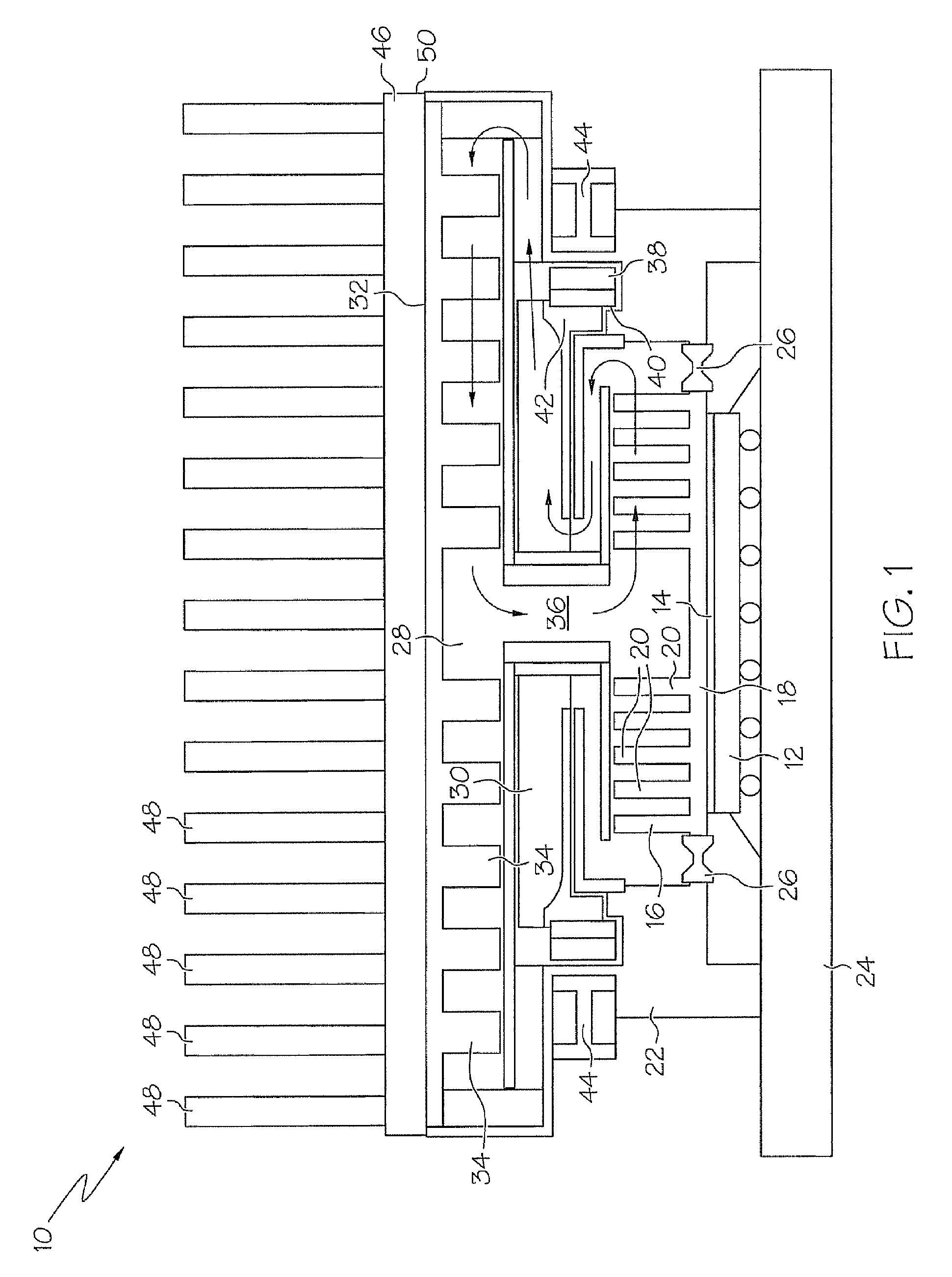
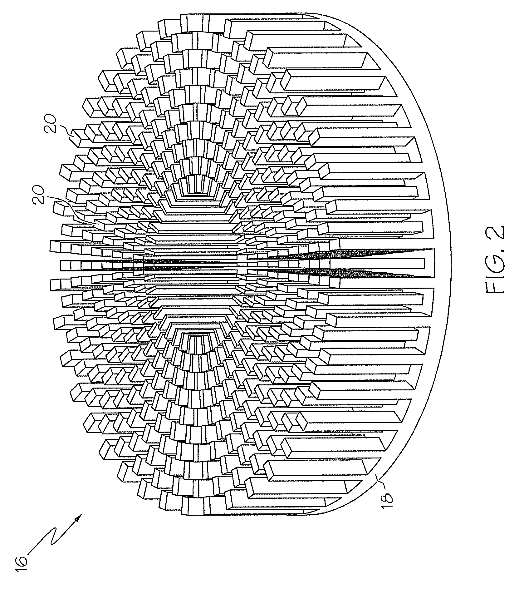
[0016]Turning now to the drawings in greater detail, it will be seen that in FIG. 1 there is an integrated active heat spreader and exchanger device 10. The device 10 is attached to a microprocessor chip 12 by a thin layer of thermal interface material (TIM) 14 at a heat spreader 16. The heat spreader 16 is made of a conductive material and comprises a spreader plate 18 with a plurality of spreader fins 20 extending from the plate 18. In one embodiment, the heat spreader 16 is made of copper. In some embodiments, the heat spreader 16 may be permanently attached to the chip 12 by use of thermal epoxies, Indium / Silver based metal compounds or eutectic solder. Alternatively, the heat spreader 16 can be formed of silicon to remove a thermal mismatch with the chip 12.

[0017]The heat spreader 16 conducts heat from the chip 12 into the spreader plate 18, and into the spreader fins 20. The size and thickness of the heat spreader 16 can vary based on the application, but in one embodiment the...


PUM

PropertyMeasurementUnit
sizeaaaaaaaaaa
thicknessaaaaaaaaaa
thicknessaaaaaaaaaa

Abstract

Disclosed is an integrated active heat spreader and exchanger. The heat spreader cum exchanger includes a housing with a conductive heat spreader therein. A spreader plate of the heat spreader is in thermal contact with a microprocessor chip to be cooled and a plurality of spreader fins extending from the spreader plate. A membrane connects the heat spreader and the housing, sealing an interface between the heat spreader and the housing. A top plate, including a plurality of top plate fins, is disposed in the housing. A pump is located between the top plate fins and the spreader fins and urges fluid across the spreader fins and conducts heat from the spreader fins. The top plate fins conduct heat from the fluid and into a heat sink in thermal contact with the top plate. A heat sink plate conducts heat into heat sink fins where the heat is dissipated.

Description

TRADEMARKS[0001]IBM® is a registered trademark of International Business Machines Corporation, Armonk, N.Y., U.S.A. Other names used herein may be registered trademarks, trademarks or product names of International Business Machines Corporation or other companies.BACKGROUND OF THE INVENTION[0002]1. Field of the Invention[0003]This invention relates to electronic components, and particularly to cooling devices for microprocessors.[0004]2. Description of Background[0005]A typical air cooling scheme for high power microprocessors includes a heat sink in close contact with a microprocessor chip to be cooled. The heat sink conducts heat from the chip to heat sink fins where the heat is transferred to the atmosphere by convection. A thermal interface material (TIM) is used to achieve optimal thermal contact between the chip and the heat sink. The TIM has a relatively poor thermal conductivity (about 4 W / mK), however, so it is desirable to minimize its thickness to optimize the thermal con...

Claims


Application Information

Patent Timeline
Patent Type & Authority Patents(United States)
IPC IPC(8): H05K7/20
CPCH01L23/473H01L2924/0002Y10T29/4935H01L2924/00
Inventor KHANNA, VIJAYESHWAR D.LOHIA, ALOK K.MCVICKER, GERARDSRI-JAYANTHA, SRI M.
Owner GLOBALFOUNDRIES INC
Why Eureka
Try Eureka