
Spread spectrum demodulator employing frequency detection

a demodulator and frequency detection technology, applied in the field of demodulators, can solve the problems of large circuit space, complex and unavoidable large synchronous detection oqpsk demodulator, and achieve the effect of reducing the number of circuits

Active Publication Date: 2009-01-13
LAPIS SEMICON CO LTD
View PDF11 Cites 4 Cited by
  • Summary
  • Abstract
  • Description
  • Claims
  • Application Information

AI Technical Summary

Benefits of technology

[0009]This type of frequency detection is inherently simpler than synchronous detection. In particular, the invented demodulator does not require a carrier recovery circuit.

Problems solved by technology

These circuits take up considerable space, especially the carrier recovery circuit, which typically includes a phase-locked loop or a reverse modulator.
An OQPSK demodulator employing synchronous detection is unavoidably large and complex.

Method used


Image

  • Spread spectrum demodulator employing frequency detection
  • Spread spectrum demodulator employing frequency detection
  • Spread spectrum demodulator employing frequency detection

Examples


first embodiment

[0030]Referring to FIG. 4, the first embodiment is a demodulator 10 comprising a frequency detector 11, a chip data decision unit 12, a timing recovery unit 13, a correlation unit 14, a maximum value selector 15, and a data converter 16.

[0031]The frequency detector 11 receives a modulated signal MS1, performs frequency detection, and outputs a frequency-detected signal DT1. The type of frequency detection performed is also known as frequency-shift keying (FSK) demodulation, and the detected signal DT1 will also referred to below as FSK demodulated data. Although the size of the frequency detector (FSK demodulator) 11 depends on the specific frequency detection method employed, the frequency detector 11 can be realized in a much smaller circuit than a conventional synchronous detector.

[0032]The modulated signal MS1 is a direct-sequence spread spectrum communication signal modulated according to conditions (a) to (d) above. If the modulated signal MS1 has the upper waveform shown in F...

second embodiment

[0056]A second embodiment will be described below, focusing on the differences from the first embodiment.

[0057]The demodulator in the second embodiment takes advantage of the paired relationship among the correlation coefficients shown in FIG. 8 to reduce the number of correlators.

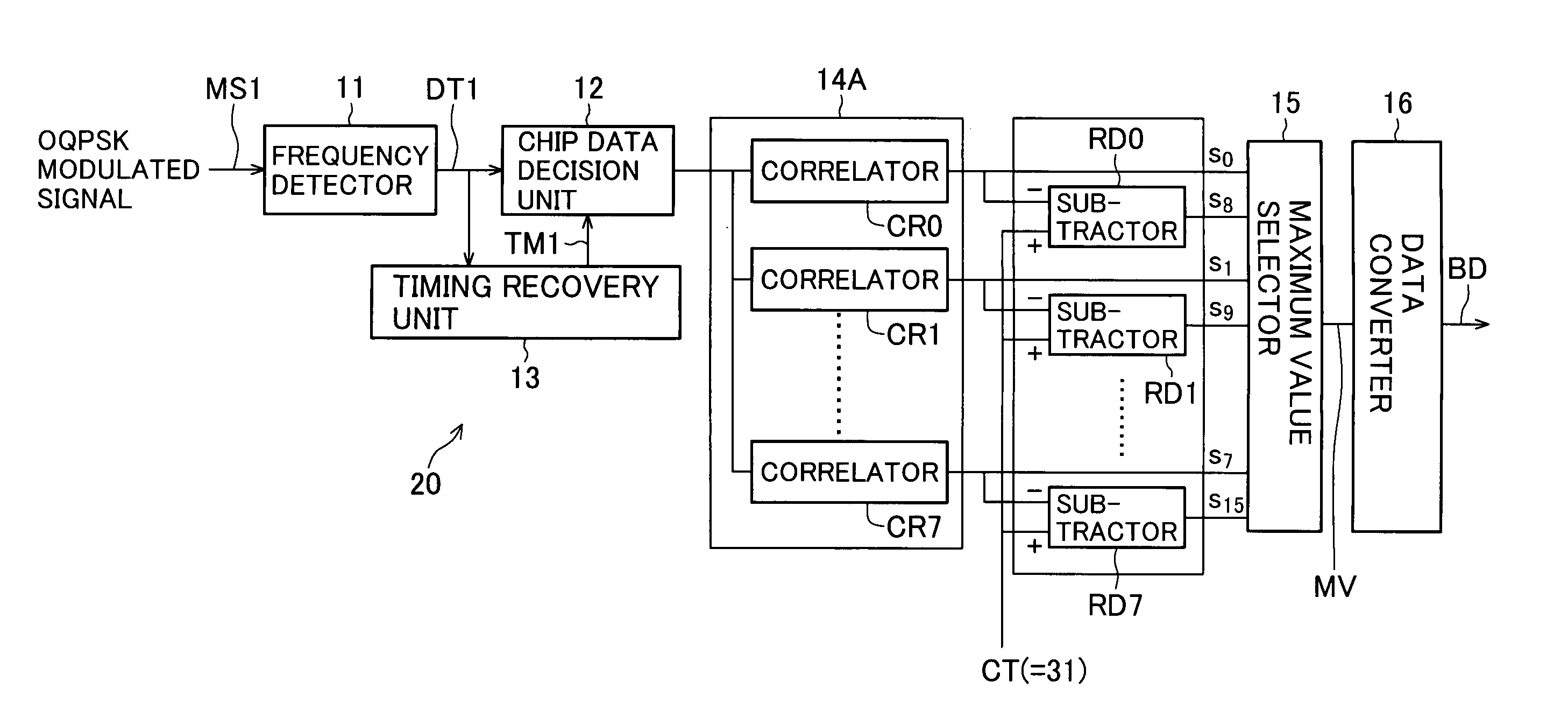
[0058]Referring to FIG. 10, the second embodiment is a demodulator 20 comprising a frequency detector 11, a chip data decision unit 12, a timing recovery unit 13, a correlation unit 14A, a maximum value selector 15, a data converter 16, and a subtraction unit 21. The number of correlators included in the correlation unit 14A is half the number in the correlation unit in the first embodiment: whereas the correlation unit 14 in the first embodiment includes sixteen correlators CR0 to CR15, the correlation unit 14A in the second embodiment includes only eight correlators CR0 to CR7. The subtraction unit 21 includes eight subtractors RD0 to RD7.

[0059]The frequency detector 11, chip data decision unit 12, timin...


PUM


Abstract

A simplified spread spectrum demodulator uses a frequency detector to demodulate a modulated spread spectrum signal to obtain successive chip values. A correlation unit correlates the successive chip values with fixed sequences of correlation coefficients to generate correlation values. A decision circuit selects one of the correlation values to decide what symbol the spread spectrum signal represents. The correlation coefficients are obtained by applying the same modulation method as used to modulate the spread spectrum signal, and then the same demodulation method as used by the frequency detector, to the sequences of chips representing different symbols. Since synchronous detection is not employed, no carrier recovery circuit is needed.

Description

BACKGROUND OF THE INVENTION[0001]1. Field of the Invention[0002]The present invention relates to a demodulator suitable for use in, for example, a direct-sequence spread spectrum communication system employing offset quadrature phase-shift keying (OQPSK) modulation.[0003]2. Description of the Related Art[0004]Conventional OQPSK demodulators have been described in various publications of the Institute of Electronics, Information and Communication Engineers (IEICE) of Japan, including IEICE SB-3-5 (1988, p. 1-564), IEICE B-150 (1991, p. 2-150), IEICE B-200 (1992, p. 2-200), and IEICE SAT 92-2 (1992, pp. 3-8). These demodulators generally employ synchronous detectors that compare the phase of the received OQPSK modulated signal with the phase of a synchronized reference carrier signal. Various synchronous detection methods are employed, but all require at least a carrier recovery circuit to generate the reference carrier signal from the received OQPSK signal, a clock recovery circuit, ...

Claims


Application Information

Patent Timeline
Patent Type & Authority Patents(United States)
IPC IPC(8): H03D1/04H04B1/22H04L27/06H04L27/10H04L27/148H04B1/707H04L27/22
CPCH04B1/707H04L27/22
Inventor MIZUNO, KOUTARO
Owner LAPIS SEMICON CO LTD
Learn More