Reverse current relay

Inactive Publication Date: 2009-01-20
SCHNEIDER ELECTRIC IND SAS
View PDF3 Cites 19 Cited by
  • Summary
  • Abstract
  • Description
  • Claims
  • Application Information

AI Technical Summary

Benefits of technology

[0010]Advantageously, the base may also have a compartment for housing a communication add-on, between the protection module and the compartment for add-on auxiliary con

Problems solved by technology

The hybrid nature of the operation of the electromagnet and its n

Method used


Image

  • Reverse current relay
  • Reverse current relay
  • Reverse current relay

Examples


Embodiment Construction

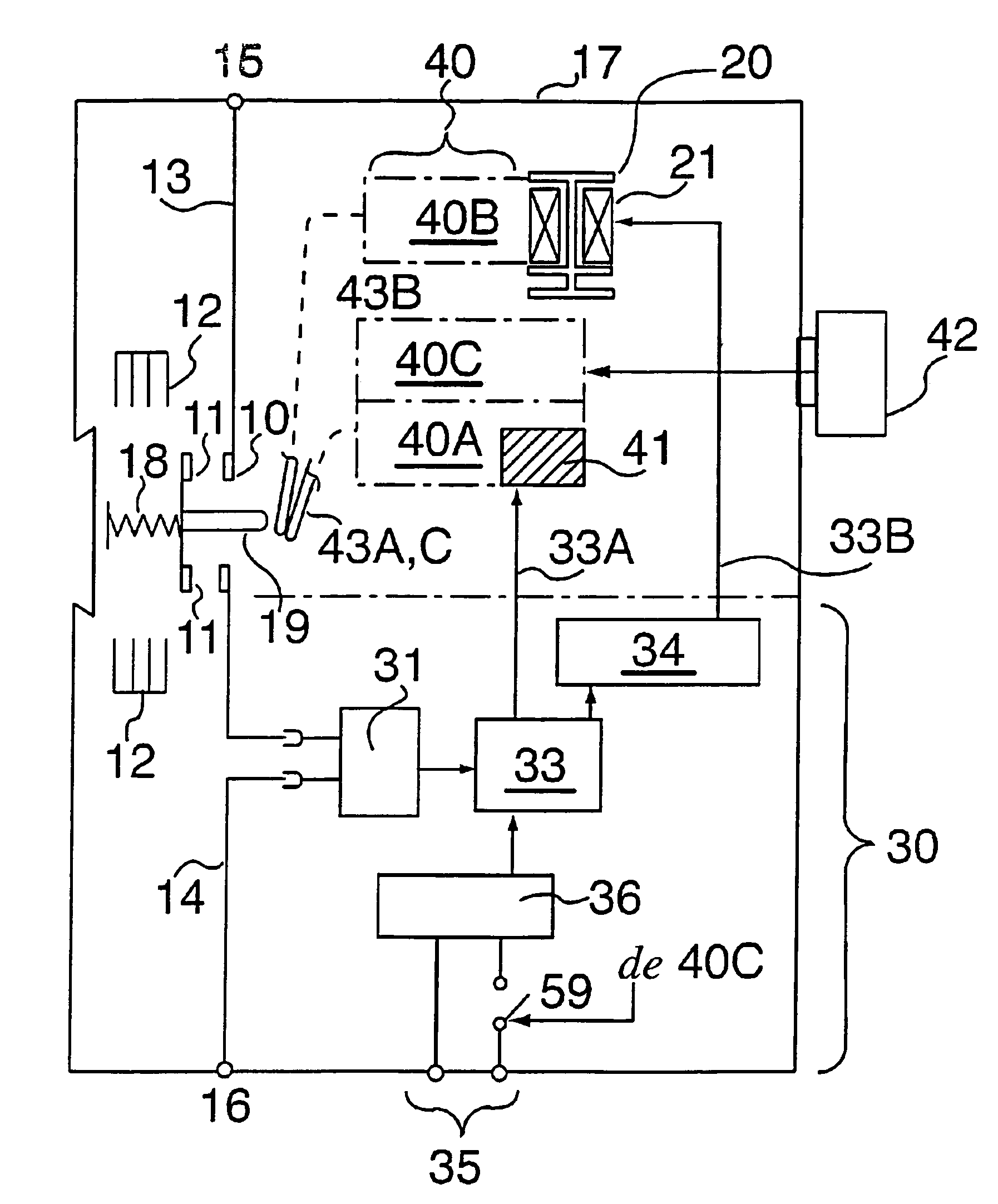
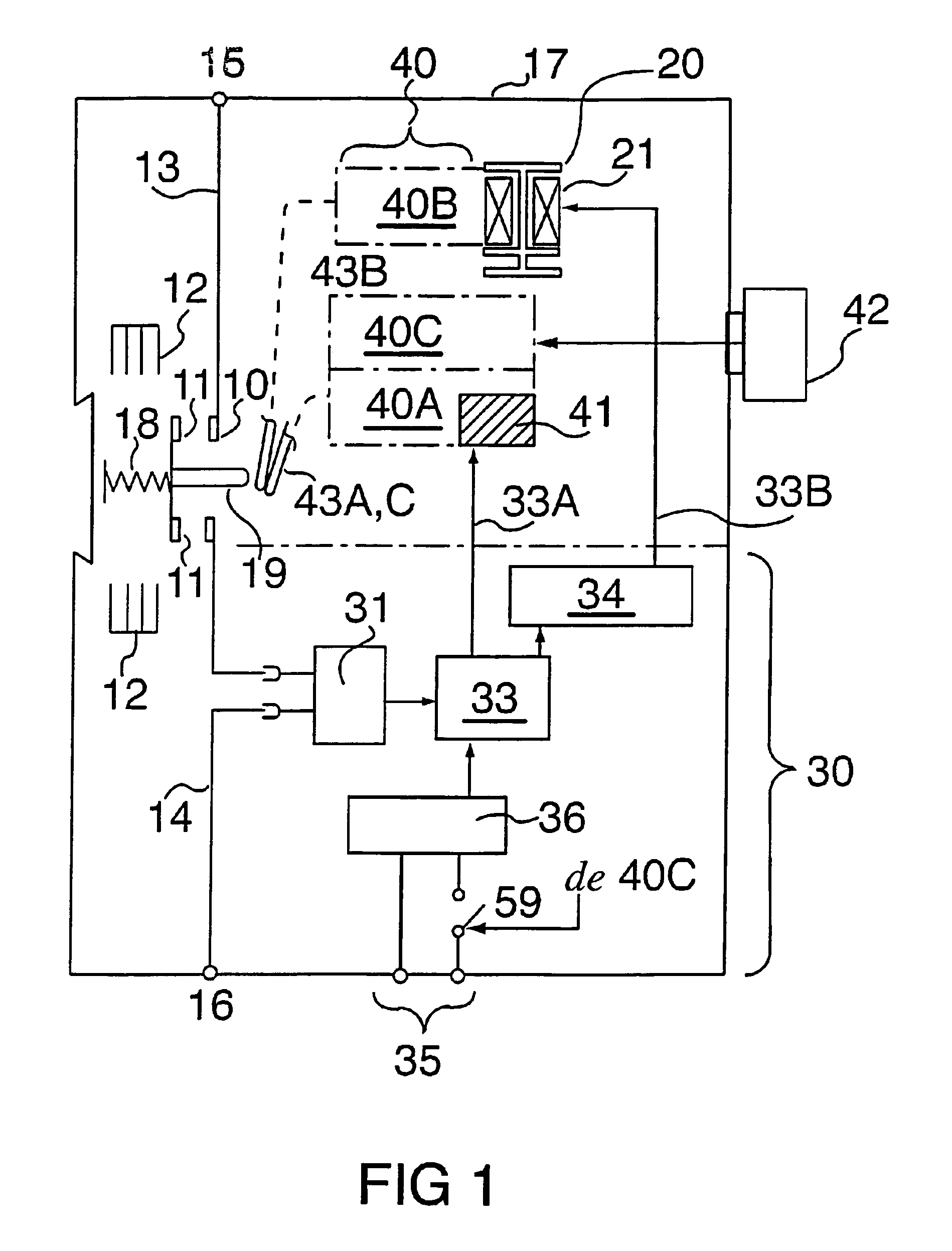
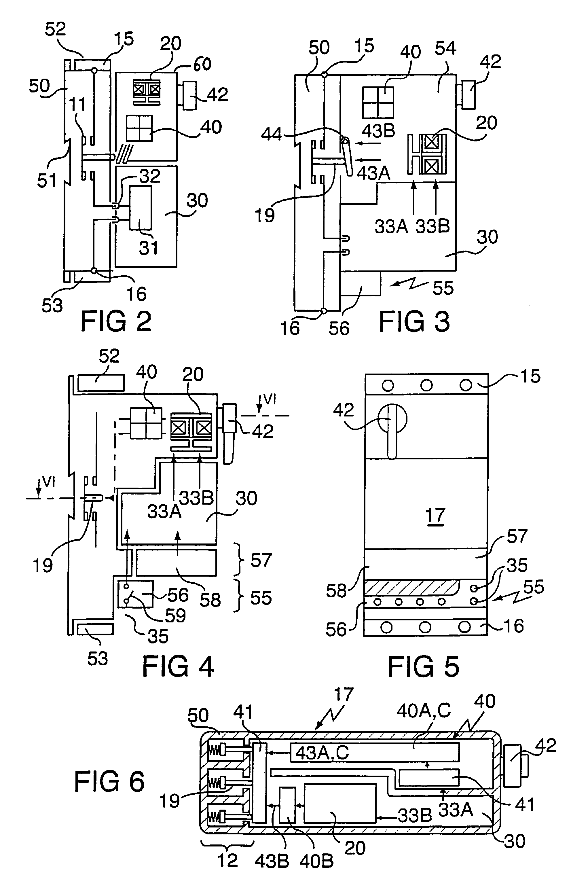
[0015]The contactor-circuit breaker comprises several contactor poles fitted with fixed contacts 10 and mobile contacts 11 associated with extinguishing chambers 12. The fixed contacts 10 are connected by power conductors 13, 14 to source power terminals 15 and load power terminals 16 placed in the equipment housing 17 or on terminal blocks fitted on the housing. For each pole, the mobile contacts 12 are laid out on a bridge forced in the closing direction by a spring 18 and in the opening direction by a pusher 19.

[0016]The contactor-circuit breaker comprises a monostable or bistable type electromagnet 20 and an electronic protection and control device 30; the end purpose of the electromagnet and the protection device is to act on the pushers 19 of the various poles. Note that the electromagnet 20 is of the DC type and it is independent of the power supply voltage, for example of the network, whereas different protection and control device 30 are provided as a function of the power ...


PUM


Abstract

Contactor-circuit breaker comprising a control electromagnet and a protection device both capable of acting on mobile contacts in response respectively to a deliberate control and to a detected electrical fault, through a multi-pole device. An electromagnetic tripping device (41) is added onto a contact control mechanism (40). The protection device (30), preferably interchangeable, is connected to the electromagnet (20) through a control line (33B) and to the control mechanism (40) through a trip line (33A) so that it outputs an electrical power supply to the electromagnet on the control line, and in the case of a fault, a trip signal on the trip line. The electromagnet (20) is of the DC type, and the protection device (30) adapts its power supply voltage.

Description

BACKGROUND OF THE INVENTION[0001]This invention relates to a contactor-circuit breaker comprising poles with separable contacts, a control electromagnet to control these contacts, and a protection device associated with a tripping device.[0002]A contactor-circuit breaker is an electrical device used to deliberately control the power supply and to break lines carrying a load such as a motor (in other words to switch this load on and off) using an electromagnet which is specific to its “contactor” part, and to automatically break the load circuit using the protection device which is specific to its “circuit breaker” part, as soon as the protection device detects an electrical fault such as a short circuit on at least one of the lines.[0003]In this type of equipment, the electromagnet and the protection device each use a multi-pole device to act on the mobile contacts in response to a deliberate control and detection of an electrical fault, respectively. The tripping device is capable ...

Claims


Application Information

Patent Timeline
IPC IPC(8): H01H63/02H01H71/02H01H71/68H01H71/08H01H71/12H01H71/46H01H71/74H01H73/00H01H73/36H01H83/02H01H89/08
CPCH01H89/08H01H71/0228H01H71/082H01H71/123H01H71/465Y04S20/14H01H2300/03Y02B90/224H01H71/7409Y02B90/20H01H73/04
Inventor BAURAND, GILLESLEGLAYE, DOMINIQUETELLIER, JEAN-PIERRE
Owner SCHNEIDER ELECTRIC IND SAS
Why Eureka
Try Eureka