Flow operated orienter

a flow-operated, wellbore technology, applied in the direction of directional drilling, interengaging clutches, borehole/well accessories, etc., can solve the problems of affecting the average drilling rate, requiring each drilling stop, and significant non-productive time, so as to achieve effective straight drilling

Inactive Publication Date: 2009-01-27
WEATHERFORD TECH HLDG LLC
View PDF113 Cites 28 Cited by
  • Summary
  • Abstract
  • Description
  • Claims
  • Application Information

AI Technical Summary

Benefits of technology

[0012]Some embodiments of the present invention generally provide an apparatus that may be used in a coiled tubing drillstring and that can switch between effectively straight drilling and curved drilling without halting drilling. Methods for steering a coiled tubing drillstring are also provided.

Problems solved by technology

One significant drawback to directional drilling with the ratcheting orienter described above is the fact that drilling must be stopped each time the orienter is actuated.
This non-productive time is significant and has an adverse affect on the average drilling rate.
A second drawback to directional drilling with the ratcheting orienter relates to its inability to drill an effective straight wellbore section.
When drilling with coiled tubing and a ratcheting orienter, continuous rotation is not possible.

Method used


Image

  • Flow operated orienter
  • Flow operated orienter
  • Flow operated orienter

Examples


Embodiment Construction

[0024]The term “coupled” as used herein includes at least two components directly coupled together or indirectly coupled together with intervening components coupled therebetween.

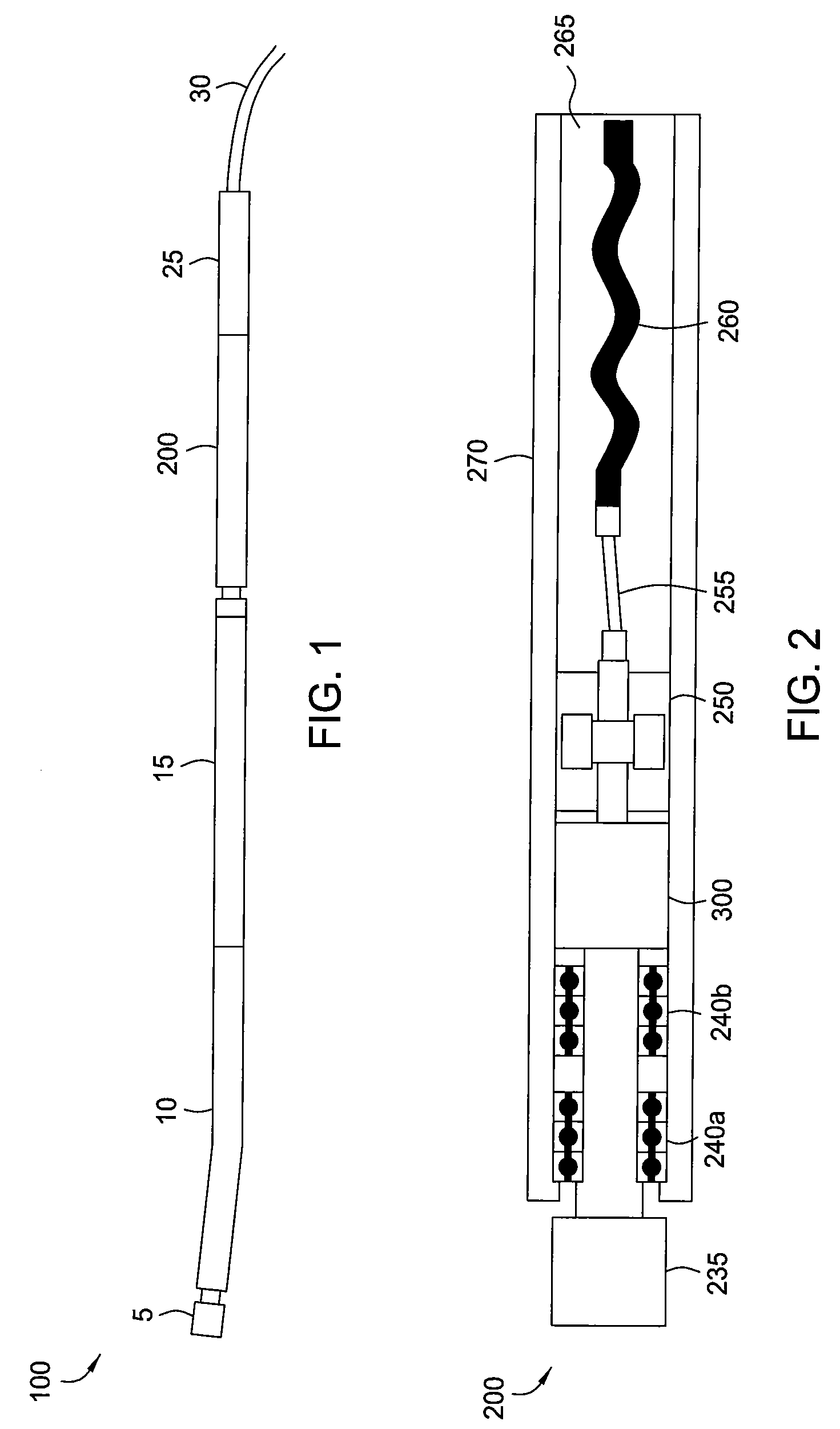
[0025]FIG. 1 is a diagram of a coiled tubing Bottom Hole Assembly (BHA) 100, according to one embodiment of the present invention. The coiled tubing BHA 100 includes: a drill bit 5, a bent-housing drilling motor 10, Measurement While Drilling (MWD) module 15, orienter 200, and connector 25. As discussed above, bent-housing drilling motor 10 will cause drilling in a curved direction provided that the drillstring is rotationally fixed. Alternatively, a bent sub and a straight-housing motor could be used instead of the bent-housing motor 10. The bent-housing motor 10 is a mud motor, which harnesses energy from drilling fluid by channeling it between a profiled rotor and stator, thereby imparting the energy into rotational motion of the rotor. The drill bit 5 is coupled to the rotor of the motor 10.

[0026]MWD mo...


PUM


Abstract

Some embodiments of the present invention generally provide an apparatus that may be used in a coiled tubing drillstring and that can switch between effectively straight drilling and curved drilling without halting drilling. Methods for steering a coiled tubing drillstring are also provided. In one embodiment, an apparatus for use in drilling a wellbore is provided. The apparatus includes a mud motor; a housing; an output shaft; and a clutch actuatable between two positions. The clutch is configured to rotationally couple the mud motor to the output shaft when the clutch is in a first position as a result of fluid being injected through the clutch at a first flow rate, and rotationally couple the output shaft to the housing when the clutch is in a second position as a result of fluid being injected through the clutch at a second flow rate.

Description

CROSS-REFERENCE TO RELATED APPLICATIONS[0001]This application claims benefit of U.S. Provisional Patent Application No. 60 / 680,731, filed May 13, 2005, which is hereby incorporated by reference in its entirety.BACKGROUND OF THE INVENTION[0002]1. Field of the Invention[0003]Embodiments of the present invention generally relate to directional drilling in a wellbore.[0004]2. Description of the Related Art[0005]Conventional directional drilling with jointed pipe is accomplished through use of a Bottom Hole Assembly (BHA) consisting of a bent housing directional drilling motor and directional Measurement While Drilling (MWD) tool in the following fashion.[0006]To drill a curved wellbore section, the drillstring is held rotationally fixed at the surface and the drilling motor will drill a curved wellbore in the direction of the bend in its outer housing. This is termed “slide” drilling because the entire drillstring slides along the wellbore as drilling progresses. The wellbore trajectory...

Claims


Application Information

Patent Timeline
Patent Type & Authority Patents(United States)
IPC IPC(8): E21B7/04
CPCE21B7/067E21B17/03E21B23/04E21B7/06E21B7/10F16D11/00E21B7/061E21B29/06
Inventor HORST, CLEMENS L.TEALE, DAVID W.HEATON, MARK
Owner WEATHERFORD TECH HLDG LLC
Why Eureka
Try Eureka