Unlock instant, AI-driven research and patent intelligence for your innovation.

Pre-bias protection circuit for converter

a protection circuit and converter technology, applied in the field of converter circuits, can solve problems such as system problems

Active Publication Date: 2009-01-27
INFINEON TECH AMERICAS CORP
View PDF2 Cites 47 Cited by
  • Summary
  • Abstract
  • Description
  • Claims
  • Application Information

AI Technical Summary

Benefits of technology

The solution effectively prevents pre-bias voltage discharge during converter startup, minimizing glitches and ensuring stable system operation by gradually increasing the duty cycle of the low-side switch control signal, thus maintaining the pre-bias voltage.

Problems solved by technology

Discharging the pre-bias voltage may result in glitches and cause problems in systems, e.g., multi-processor systems.

Method used


Image

  • Pre-bias protection circuit for converter
  • Pre-bias protection circuit for converter
  • Pre-bias protection circuit for converter

Examples


Embodiment Construction

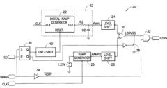
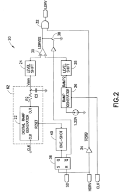
[0020]The present invention provides a way of preventing discharge of the pre-bias voltage in the converter circuits. This is achieved by controlling the duty cycle on-time of the low-side transistor. FIG. 2 illustrates a circuit 20 that receives the high-side switch control signal Hdrv and processes it into the low-side switch control signal Ldrv. The circuit 20 includes a digital ramp generator circuit 22 with a corresponding level shifter circuit 24, an analog ramp generator circuit 26 also with a corresponding level shifter circuit 28. Both ramp generator circuits 22 and 26 receive a clock signal Clk. An output of the digital ramp generator circuit 22 is filtered using a Low Pass Filter including a register R2 and a capacitor C2. An output of the level shifter circuits 24 and 28 is compared by a comparator circuit 30. Further, an AND circuit 32 is used to AND a signal LdrvSS of the comparator circuit 30 with an inverse of the high-side switch control signal Hdrv, inverted in the...


PUM


Abstract

A pre-bias protection circuit for a converter circuit including a switching stage having high-and low-side switches connected in series at a switching node and an output stage connected to the switching node having a capacitor having a pre-existing pre-bias voltage at startup of the converter circuit, the pre-bias protection circuit controlling discharge of the pre-bias voltage when the low-side switch is turned ON during a start up of the converter circuit. The pre-bias protection circuit includes a first circuit for providing a first output; a second circuit providing a second output; and a comparator circuit for comparing the first output and the second output and producing a third output comprising a pulse width modulated signal for driving the low side switch such that the pulse width modulated signal starts with a small duty cycle and thereafter increases to a larger duty cycle, thereby to prevent the pre-bias voltage from discharging during startup.

Description

CROSS-REFERENCE TO RELATED APPLICATION[0001]This application is based on and claims priority to U.S. Provisional Patent Application Ser. No. 60 / 820,551, filed on Jul. 27, 2006 and entitled PREBIAS PROTECTION CIRCUIT FOR CONVERTER, the entire contents of which are hereby incorporated by reference herein.BACKGROUND OF THE INVENTION[0002]The present invention relates to converter circuits and more particularly to pre-bias protection circuits for the converter circuits.[0003]Voltage, pre-existing at an output stage of a converter, for example, a converter circuit 8 having a transistor stage 10 illustrated in FIG. 1, prior to start up is referred to as pre-bias voltage. When the converter circuit 8 starts up, high- and low-side switches 12 and 14 of the transistor stage 10 will be driven by high- and low-side switch control signals Hdrv and Ldrv from respective high- and low-side gate drivers. When the low-side switch control signal Ldrv is applied to the low-side switch 14 during startu...

Claims


Application Information

Patent Timeline
Patent Type & Authority Patents(United States)
IPC IPC(8): G05F1/575G05F1/40
CPCH02M1/36H02M7/53803Y10S323/901
Inventor PARTO, PARVIZCHEN, YANG
Owner INFINEON TECH AMERICAS CORP