Tray with adjustable stacking heights

a stacking height and adjustable technology, applied in the field of containers, can solve the problems achieve the effects of reducing the overall volume of the nested tray, reducing the stiffness of the support, and large cutting outs

Inactive Publication Date: 2009-02-03
REHRIG PACIFIC CO INC
View PDF177 Cites 19 Cited by
  • Summary
  • Abstract
  • Description
  • Claims
  • Application Information

AI Technical Summary

Benefits of technology

[0005]A tray includes a floor and a pair of opposed side walls, each having a cutout, one of which is larger to form the dropside. A pair of bail members are pivotably and slidably secured to opposed end walls. The bail members are supported by the end walls at a plurality of selected heights. Thus, stacking orientation of the trays is independent of the stacking height, and the dropsides can be aligned at any stacking height. The bail member is arranged to provide structural support to the dropside of a similar tray stacked thereon. The stiffness of the support is increased by the design of the bail member, which has a support portion with an elongated cross section. The elongated cross section is maintained in a vertical orientation when the bail member is in any of the stacking positions. In this manner, the dropside can have a large cutout without deflecting substantially during use.
[0006]Additionally, when the bail members are moved to a nesting position, the empty trays can be substantially nested within one another, thereby reducing the overall volume of the nested trays.

Problems solved by technology

Additionally, when the bail members are moved to a nesting position, the empty trays can be substantially nested within one another, thereby reducing the overall volume of the nested trays.

Method used


Image

  • Tray with adjustable stacking heights
  • Tray with adjustable stacking heights
  • Tray with adjustable stacking heights

Examples


first embodiment

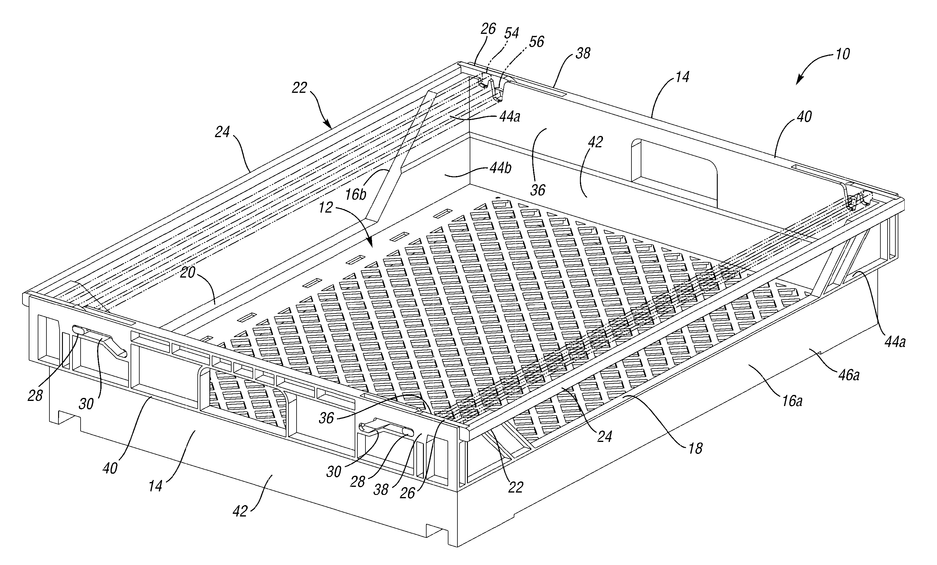
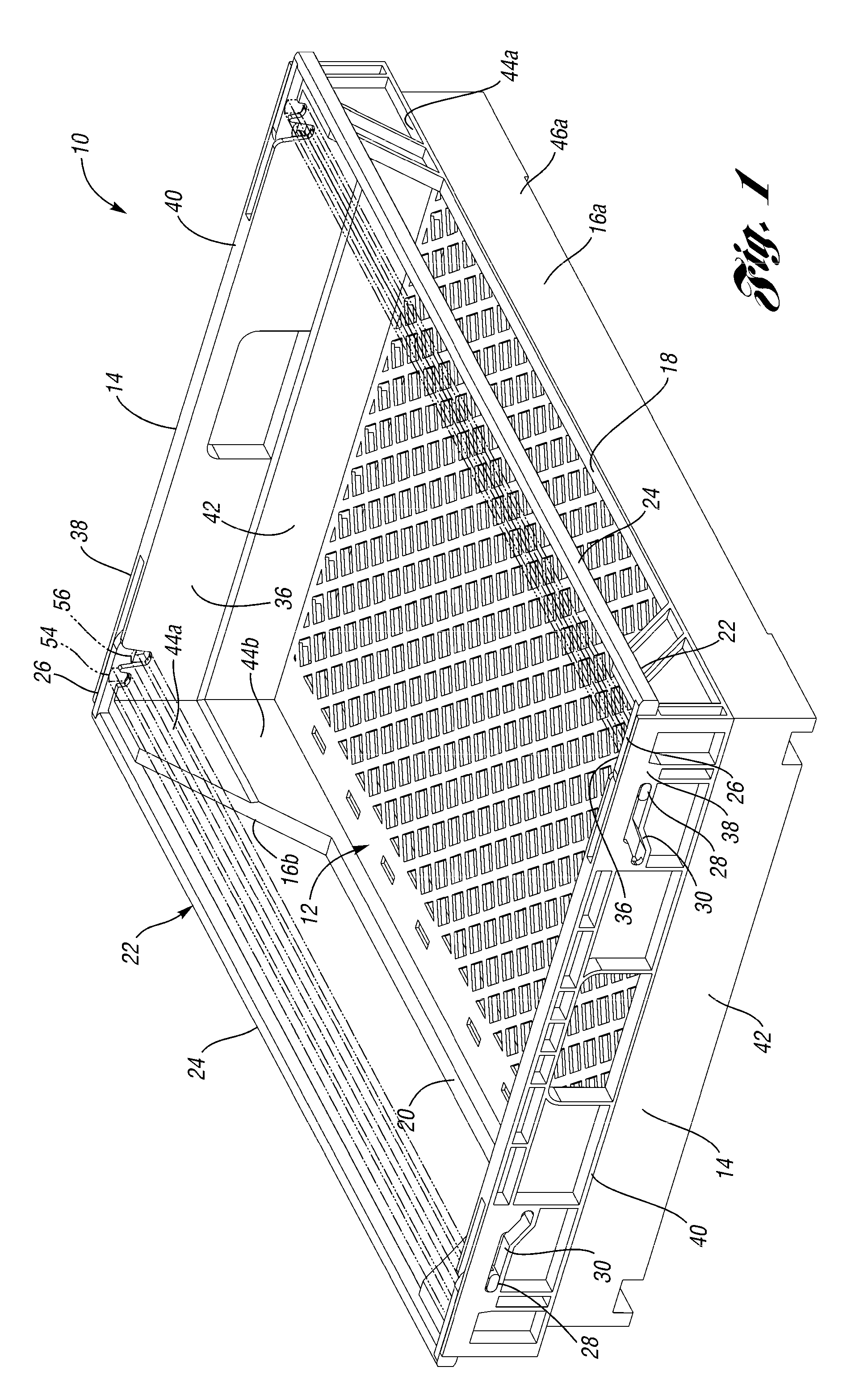
[0024]A tray 10 according to the present invention is shown in FIG. 1. The tray 10 includes a floor 12 and a pair of opposed end walls 14 extending upwardly from ends of the floor 12. A first side wall 16a extends upwardly from a first side of the floor 12 and a second side wall 16b extends upwardly from a second side of the floor 12. The first side wall 16a includes a first cutout 18 opening upwardly in a middle portion of the first side wall 16a. The second side wall 16b includes a second cutout 20 or window opening upwardly in the middle portion of the second side wall 16b.

[0025]A pair of bail members 22 are pivotably and slidably secured at opposite ends to the end walls 14. Each bail member 22 includes a support portion 24 extending from one end wall 14 to the other. The support portion 24 is connected at each end to a support arm 26 having an elongated pin 28 extending outwardly therefrom. Each pin 28 is trapped in a slot 30 through the end wall 14. The pin 28 can slide freel...

second embodiment

[0035]FIG. 9 is a perspective view of a tray 110 according to the invention showing the bail members 122 in multiple positions. To the extent not otherwise described or illustrated, the tray 110 is identical to that of FIG. 1 and like reference numerals will be used where possible, with a “1” preappended. The tray 110 includes side walls 116a,b. In this embodiment, the bail members 122 are vertically aligned with the upper portions 144a,b of the side walls 116a,b when in the nest position. This decreases the overall footprint of the tray 110 in the nested position.

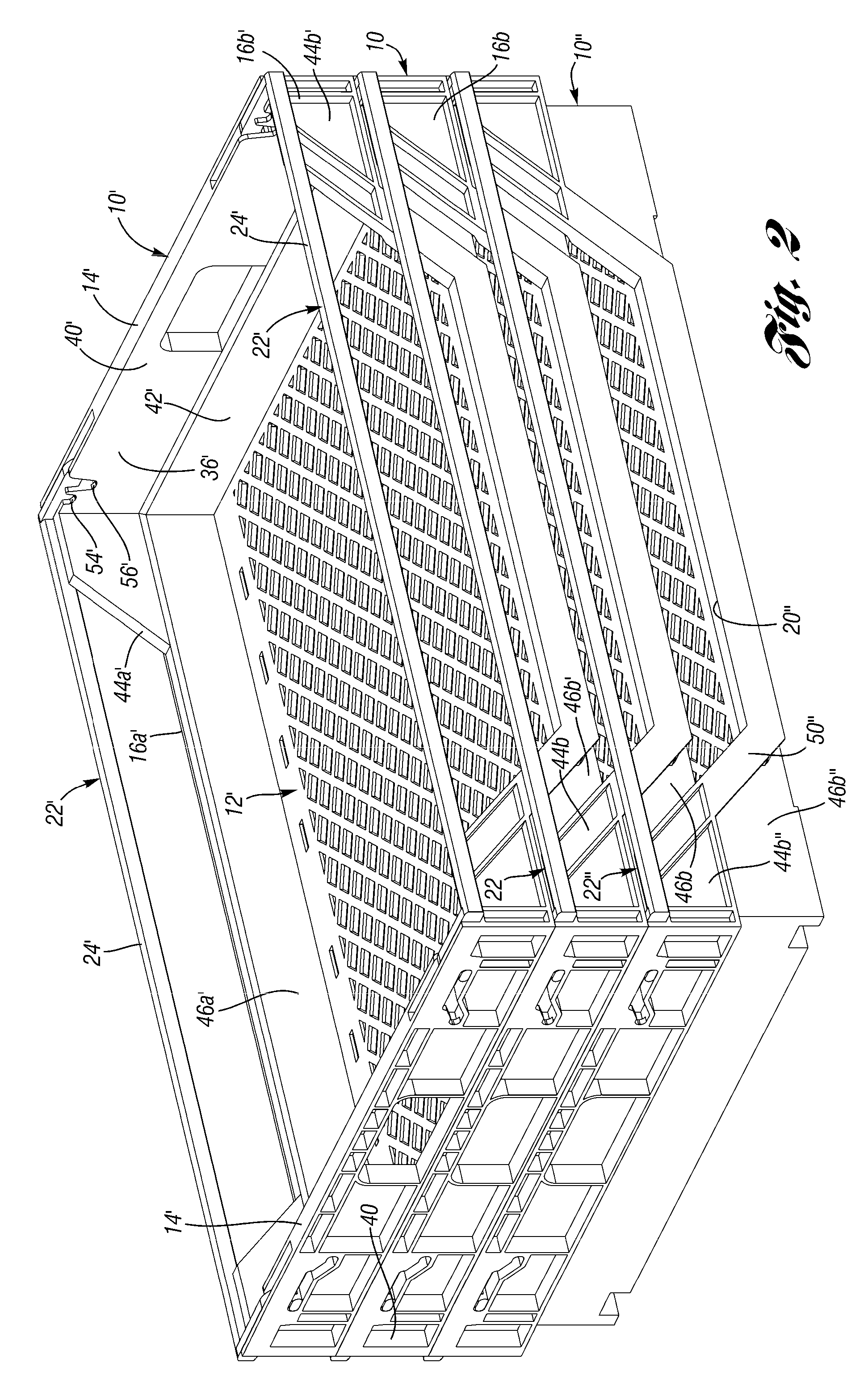
[0036]FIG. 10 is a perspective view of the tray 110 of FIG. 9 nested in a similar tray 110″ and with a similar tray 110′ nested therein. In this embodiment, the band 50 (FIG. 1) of the first embodiment is removed so that the support portion 124 of the bail member 122 directly abuts the underside of the upper portions 144a,b′ of the side walls 16a,b′ and the outer surface of the lower portions 146a, b′.

[0037]FIG. 11 is a pe...

third embodiment

[0041]FIG. 15 is perspective view of a tray 210 according to the present invention. Except as otherwise illustrated or described, the tray 210 is identical to the tray 110. Each bail member 222 includes a locating feature 225 projecting upwardly from the corners where the support portion 224 joins the arms 226. The locating feature is generally perpendicular to the support portion 224 and arms 226. The locating feature assists with blind stacking, by assisting the proper location of a prior art trays onto the tray 210, as shown in more detail in FIG. 16, described below.

[0042]Each side wall 214 includes a rail 227 extending upwardly from a middle portion thereof. Each rail 227 is aligned between the locating features 225 on opposite bail members 222. Each side wall 214 further includes a pair of columns 241 projecting outwardly. A foot 243 is formed at the bottom of each column 241. The foot is spaced outwardly from the side wall 214. The rail 227 and feet 243 make the tray 210 more...


PUM


Abstract

A tray includes a floor and a pair of opposed side walls, each having a cutout, one of which is larger to form the dropside. A pair of bail members are pivotably and slidably secured to opposed end walls. The bail members are supported by the end walls at a plurality of selected heights. The bail member is arranged to provide structural support to the dropside of a similar tray stacked thereon. The stiffness of the support is increased by the design of the bail member, which has a support portion with an elongated cross section. The elongated cross section is maintained in a vertical orientation when the bail member is in any of the stacking positions. In this manner, the dropside can have a large cutout without deflecting substantially during use.

Description

BACKGROUND OF THE INVENTION[0001]This invention relates to a container, and more particularly to a tray having adjustable stacking heights.[0002]A common tray used in bakeries has two end walls for stacking and two shorter side walls for product visibility and to allow nesting. These trays typically nest by rotating alternate trays 90degrees. They are easy to blind stack (i.e. stack above your head where it is difficult to see any locating features). However, the requirement to nest the trays in a 90degree rotation makes the footprint of the nested trays larger than a single tray and results in a low nest ratio, which is limited by the height of the side walls.[0003]In some of the known trays, one of the side walls is shorter than the other, so that it is low enough for removing product even when the trays are stacked. This is commonly called a dropside version. This lower sidewall may also be called a window. When the trays are stacked, it is advantageous for the dropsides to align...

Claims


Application Information

Patent Timeline
Patent Type & Authority Patents(United States)
IPC IPC(8): B65D21/06
CPCB65D21/062
Inventor APPS, WILLIAM P.MEISSEN, CYNTHIA R.
Owner REHRIG PACIFIC CO INC
Why Eureka
Try Eureka