
Electric machine with a brush-holding component and a plug module

a technology of electric machines and plug modules, which is applied in the direction of coupling device details, coupling device connections, mechanical energy handling, etc., can solve the problems of complex modification of the design of the intermediate frame comprising the brush holder in particular, and achieve the effect of no undesired nois

Active Publication Date: 2022-03-08
ROBERT BOSCH GMBH
View PDF20 Cites 0 Cited by
  • Summary
  • Abstract
  • Description
  • Claims
  • Application Information

AI Technical Summary

Benefits of technology

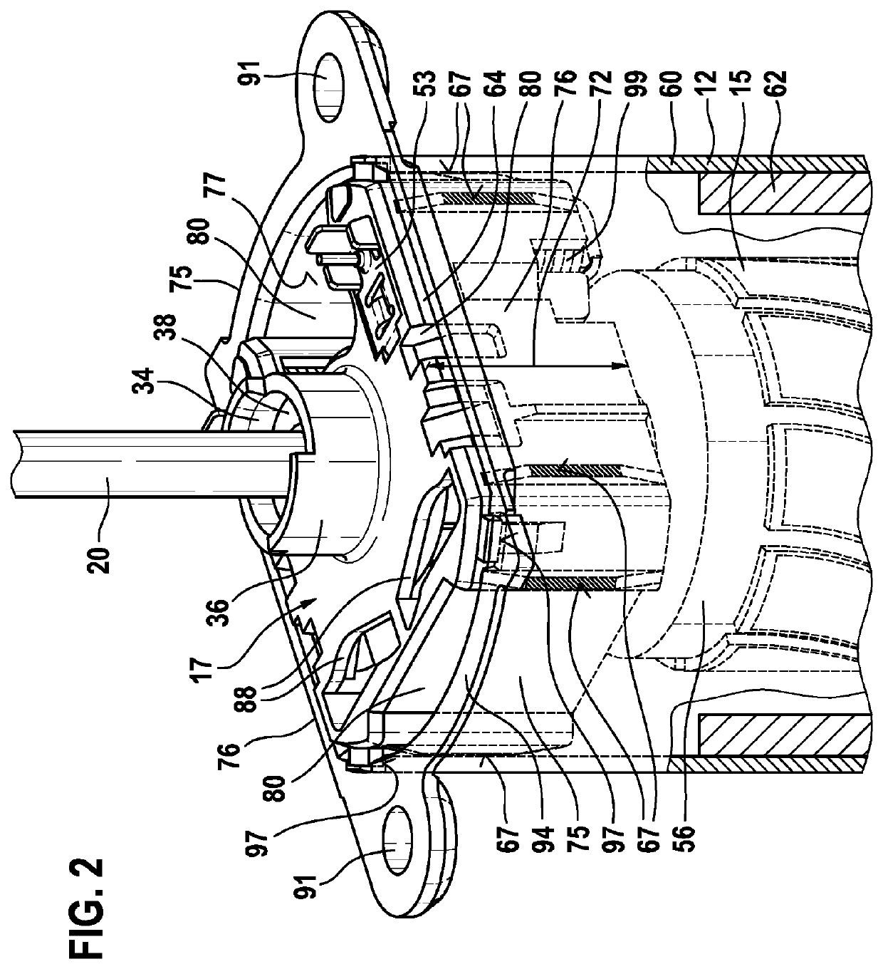
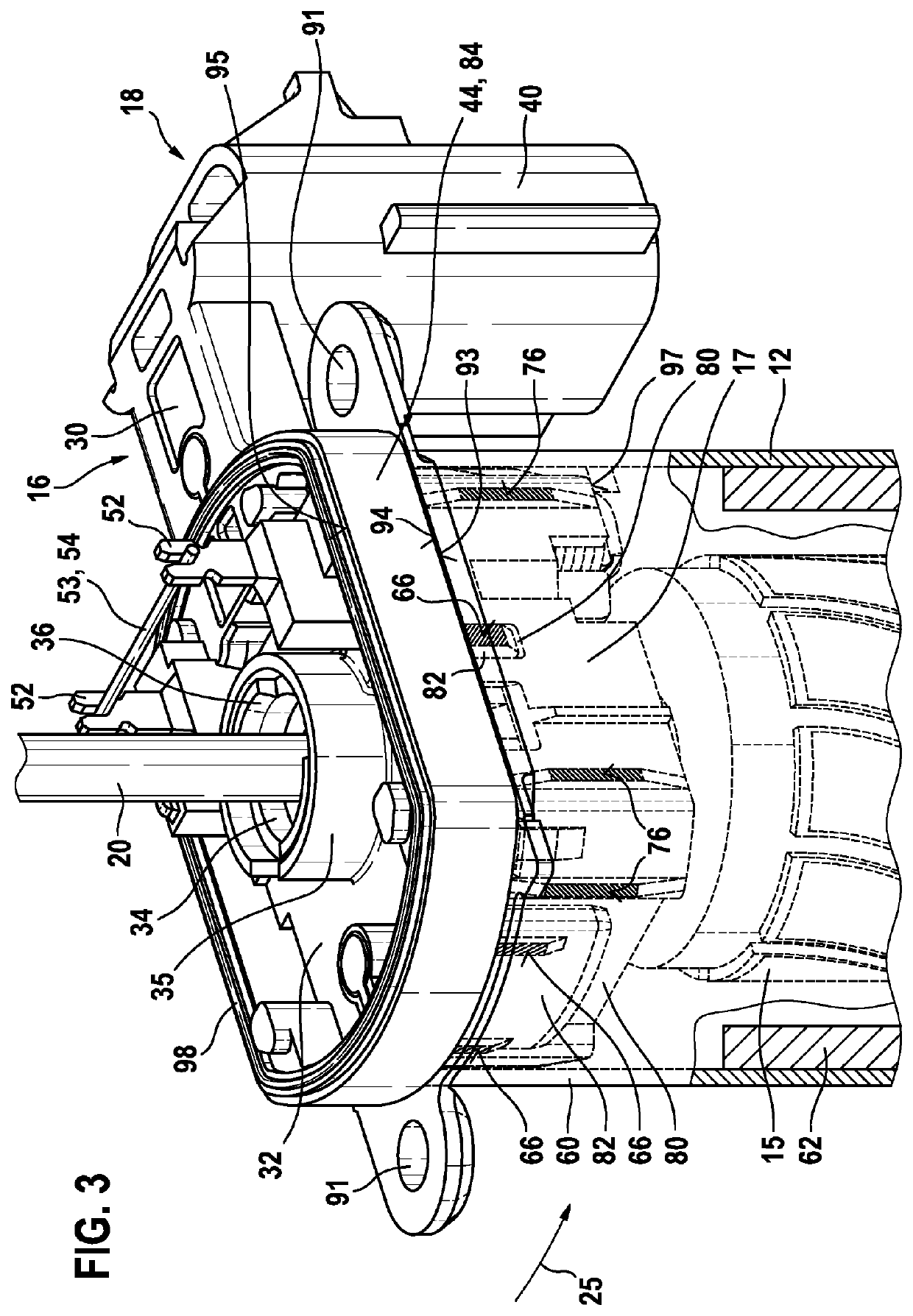
The invention is an electrical machine that has a brush holder component with a consistent design for different machine variants. This allows for easy positioning of the brushes in relation to the commutator in the pole housing, even when different plug modules are used. The brush holder component is always centered radially in the pole housing, regardless of the plug module, which prevents noises and ensures a reliable seal off between the pole housing and the gear mechanism housing. The plug module is designed to be easily matched to different customer-specific mating plugs, and can be easily varied in terms of injection-molding. The brush carrier component is axially arranged within the pole housing and is radially supported against the inner wall of the pole housing to prevent tilting or movement. The brushes are optimally shielded by the circumferential wall of the pole housing to prevent interference radiation from the electric motor. The plug module can be fitted with different interference-suppression elements and can be designed with different rotary position sensors, ensuring a reliable seal off between the pole housing and the gear mechanism housing interface.

Problems solved by technology

One disadvantage of a design of this kind is that the intermediate frame comprising the brush holder has to be equipped with different electronics components depending on the application and a total of three separate components, specifically the intermediate frame, the plug and the electronics housing, are varied.
In this case, modifying the design of the intermediate frame comprising the brush holder in particular is very complicated since the adjustment of the carbon brushes has a great influence on undesired development of noise during operation of the drive unit.

Method used


Image

  • Electric machine with a brush-holding component and a plug module
  • Electric machine with a brush-holding component and a plug module
  • Electric machine with a brush-holding component and a plug module

Examples


Embodiment Construction

[0027]FIG. 1 shows an electrical machine 10 as is used, for example, for adjusting moving parts—preferably window panes, sliding roofs or seat components—in a motor vehicle. In this case, a stator 13 is arranged in a pole housing 12, a rotor 15 being arranged within said stator and the rotor shaft 20 of said rotor extending axially from the pole housing 12 into an axially adjoining gear mechanism housing 14. In this case, the drive torque is transmitted from the rotor shaft 20 to a gear mechanism which is arranged in the gear mechanism housing 14, which gear mechanism has an output element 22 which interacts with a mechanism, not illustrated, which moves, for example, parts of a vehicle seat or a window pane in the motor vehicle. A plug module 16 is arranged between the pole housing 12 and the gear mechanism housing 14 in the axial direction 24, which plug module is electrically connected to brushes 26 of a separately manufactured brush carrier component 17 for the purpose of making...


PUM


Abstract

The invention relates to an electric machine (10) and system kits for electric machines (10), in particular for adjusting movable parts in a motor vehicle, comprising a commutator (55) which is arranged on a rotor shaft (20) and which can be connected to a power source in an electrically conductive manner by means of electric brushes (26), said brushes (26) being secured to a brush support component (17) which is directly radially supported on an inner wall (77) of a pole housing (12). The electric machine also of comprises a plug module (16) which has electric conductors (51) for connecting to an outer connection plug (18). The plug module (16) has axial protrusions (82) which engage into corresponding axial recesses (80) in the brush support component (17), wherein the axial protrusions (82) are likewise directly radially supported on the inner wall (77) of the pole housing (12) and not radially on the brush support component (17).

Description

BACKGROUND OF THE INVENTION[0001]The present invention relates to an electrical machine having a brush holder component and a plug module, and also to a corresponding modular system.[0002]DE 42 25 496 A1 has disclosed an electrical drive unit in which an intermediate frame, into which a brush holder is integrated, is arranged between a pole pot and a gear mechanism housing. In this case, the drive unit is of modular construction, wherein a separate plug is arranged at different positions on the drive unit. As a result, for example, different variants with or without an electronics housing can be realized and, depending on the installation position of the drive unit, the plug connection can be adjusted in accordance with space conditions and the customer-specific mating plug. One disadvantage of a design of this kind is that the intermediate frame comprising the brush holder has to be equipped with different electronics components depending on the application and a total of three sep...

Claims


Application Information

Patent Timeline
Patent Type & Authority Patents(United States)
IPC IPC(8): H02K5/14H01R13/405H01R39/38H02K5/10H02K5/22H02K7/116H02K11/026
CPCH02K5/148H01R13/405H01R39/38H02K5/10H02K5/225H02K7/116H02K11/026H02K2213/12H02K23/66H02K2211/03
Inventor DOMSIK, ISTVANSZUCS, NORBERTBODNAR, PALUNGVARI, PETERSCHEURICH, STEPHANELLERBY, MARC
Owner ROBERT BOSCH GMBH
Learn More