
Trailing arm suspension with optimized I-beam

Active Publication Date: 2009-02-03
THE HOLLAND GROUP
View PDF21 Cites 39 Cited by
  • Summary
  • Abstract
  • Description
  • Claims
  • Application Information

AI Technical Summary

Benefits of technology

[0016]Another aspect of the present invention is to provide a suspension system for suspending a vehicle frame above a plurality of ground-engaging wheels that includes a wheel-carrying axle comprising a first end and a second end, and a pair of frame bracket assemblies each comprising a resiliently-bushed pivotable connection, wherein the frame bracket assemblies are operably coupled to opposite ends of the vehicle frame, and wherein the resilient-bushed pivotable connection comprises an elastically-deformable bushing. The suspension system also includes a pair of trailing arms each comprising a first end operable coupled to the first end and the second end of the axle, respectively, and a second end comprising an aperture that receives the bushing of one of the frame bracket assemblies therein, wherein the aperture defines an inner surface, and wherein the inner surface is nonuniform, thereby reducing a rotation of the bushing with respect to the trailing arm.
[0018]Still yet another aspect of the present invention is to provide a suspension system for suspending a vehicle frame above a plurality of ground-engaging wheels that includes a wheel-carrying axle comprising a first end and a second end, and a pair of frame bracket assemblies each comprising a resilient-bushed pivotable connection, wherein the frame bracket assemblies are operably coupled to opposite sides of the vehicle frame, and wherein the resiliently-bushed pivotable connection comprises an elastically deformable bushing. The suspension system also includes a pair of trailing arms each comprising a first end comprising a mating surface operably coupled to the first end and the second end of the axle, respectively, and a second end comprising an aperture that receives the resilient-bushed pivotable connection of the frame bracket assemblies therein, wherein the mating surface of the first end of each of the trailing arms comprises a cavity, thereby reducing a localized stress transferred from the trailing arms to the axle.
[0021]Still yet another aspect of the present invention is to provide a suspension system for suspending a vehicle frame above a plurality of ground-engaging wheels that includes a wheel-carrying axle comprising a first end and a second end, a pair of frame bracket assemblies operably coupled to opposite sides of the vehicle frame, and a pair of air springs each comprising a flexible boot. The suspension system also includes a pair of trailing arms each comprising a first end operably coupled to the first end and the second end of the axle, respectively, a second end operably coupled to one of the frame bracket assemblies, and a top surface comprising a first portion and a second portion, wherein the second portion is adapted to support one of the air springs thereon, and wherein the second portion extends above the first portion, thereby substantially reducing an amount of contact between the trailing arm and the boot of the air spring when the air spring is in a deflated condition.
[0022]Still yet another aspect of the present invention is to provide a suspension system for suspending a vehicle frame above a plurality of ground-engaging wheels that includes a wheel-carrying axle comprising a first end and a second end, and a pair of frame bracket assemblies operably coupled to opposites sides of the vehicle frame. The suspension system also includes a pair of trailing arms each comprising a first end operably coupled to the first end and the second end of the axle, respectively, and a second end operably coupled to one of the frame bracket assemblies, wherein the first end of each trailing arm comprises a tube-shaped portion having a slot extending along the length thereof for receiving the axle therein during assembly. The suspension system further includes a pair of spacer assemblies each operably coupled with the trailing arms and spanning the slot of the first end, thereby reducing an amount of flexure of each trailing arm proximate the coupling between the trailing arm and the axle.
[0023]The present inventive trailing arm and associated suspension system results in an increased operational lifespan for the associated system, reduces the overall weight, while simultaneously providing increased structural integrity and reducing production and operation costs. The trailing arm disclosed herein is more durable, more wear resistant, efficient in use, and is particularly well adapted for the proposed use.

Problems solved by technology

This approach results in sections of the beam having more material than is necessary for the maximum stress imposed on the beam at that section.
This excess material adds to the cost and weight of the beam.
Moreover, the welds induce stresses into the beam that can contribute to premature failure of the beam.
However, such detailed welding techniques can also increase the cost of fabrication and the weight.
Welded connections can induce in the axle stresses and cracks that can contribute to premature failure of the axle.
In previously known systems, significant wear of the trailing arms may occur proximate the hanger brackets during operation of the associated suspension system.
The contact between the beams and hanger bracket causes excessive wear requiring the replacement of the beams to avoid catastrophic failure of the beams and / or bushings.
However, the construction of these specialized bushings is more expensive than bushings that do not include such apertures.
During operation of the associated suspension system, bending stress are exerted on the axles, with localized points of stress being exerted at the locations of the connection between the trailing arms and the axles, thereby contributing to excessive stress on the axles and decreasing the useful life of the axles.
Normal operation of the suspension system also leads to wear of the boot of the air spring each time the boot is allowed to contact the associated beam.
This wear of the boot is especially prevalent during times of loading / unloading when air is not being supplied to the air springs.
Another cause of significant stress within previously known beam configurations, is the concentration of the upwardly directed load bear force exerted by the axle on the beam, and the downwardly directed forces exerted on the ends of the beam by the hanger bracket and air spring.
This bending of the each beam results in a compressive force being exerted on the axle and the connection between the beams and the axle.

Method used


Image

  • Trailing arm suspension with optimized I-beam
  • Trailing arm suspension with optimized I-beam
  • Trailing arm suspension with optimized I-beam

Examples


Embodiment Construction

[0044]For purposes of description herein, the terms “upper,”“lower,”“right,”“left,”“rear,”“front,”“vertical,”“horizontal,” and derivatives thereof shall relate to the invention as oriented in FIGS. 1-3. However, it is to be understood that the invention may assume various alternative orientations and step sequences, except where expressly specified to the contrary. It is also to be understood that the specific devices and processes illustrated in the attached drawings, and described in the following specification are exemplary embodiments of the inventive concepts defined in the appended claims. Hence, specific dimensions and other physical characteristics relating to the embodiments disclosed herein are not to be considered as limiting, unless the claims expressly state otherwise.

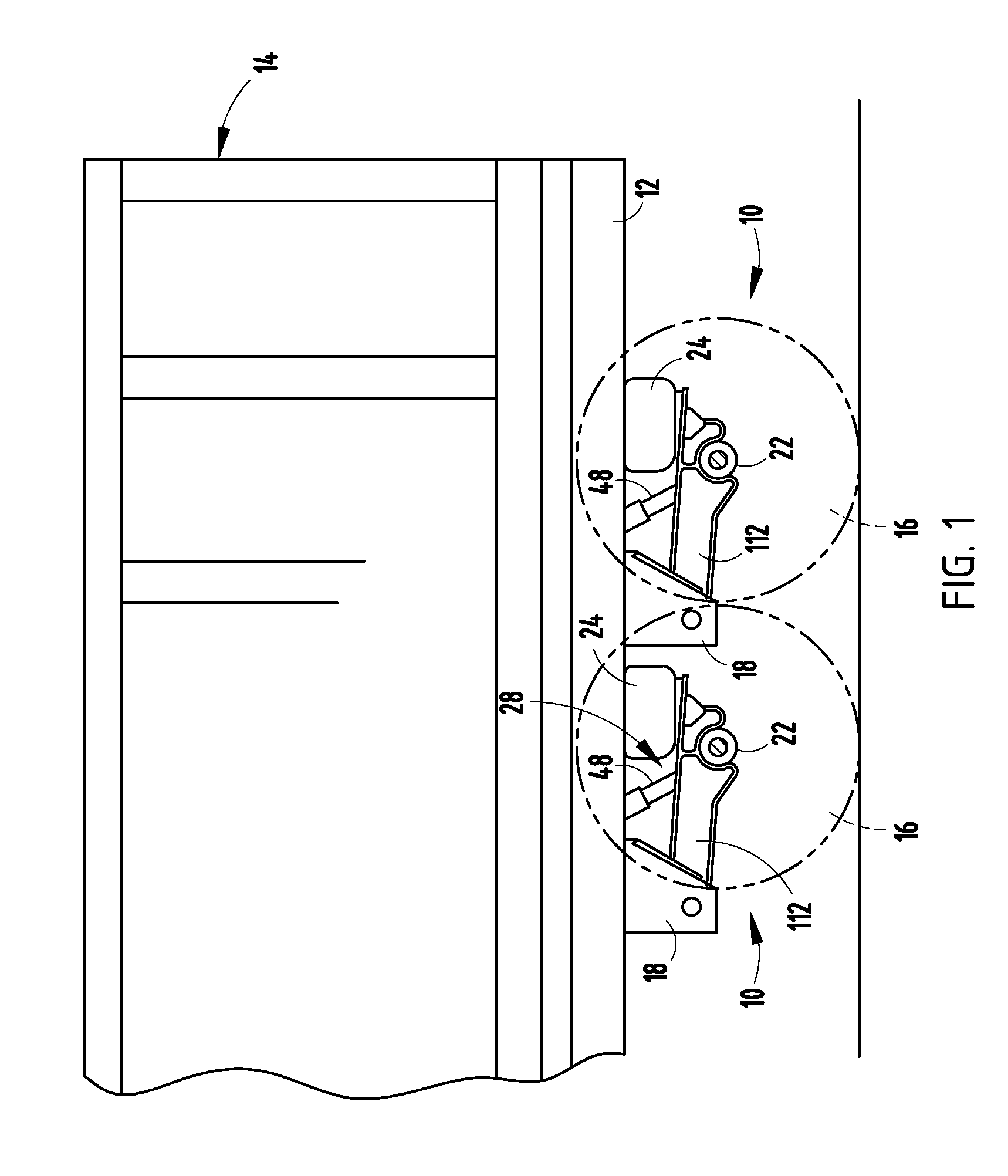
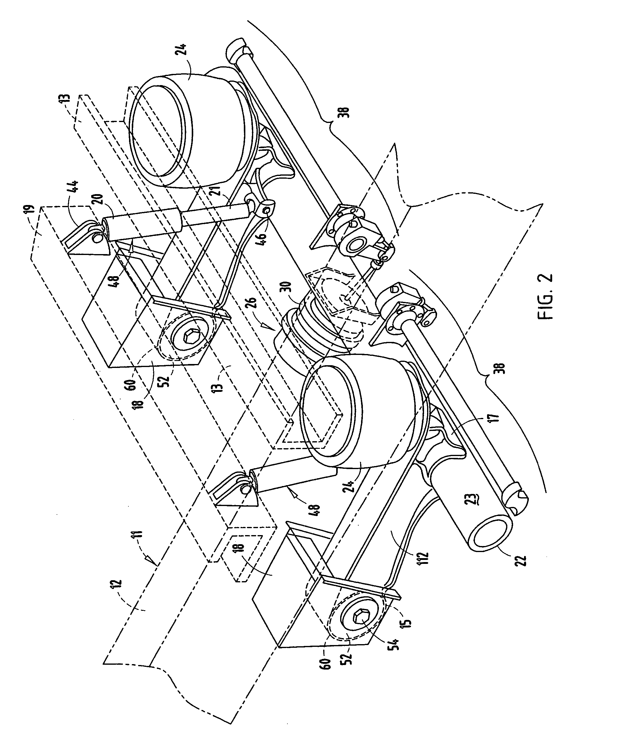
[0045]Referring now to FIGS. 1 and 2, a trailing arm suspension assembly 10 according to the invention is shown suspended from a trailer frame 11, including a trailer frame rail 12, a first crossbeam 13 (s...


PUM


Abstract

A suspension system for suspending a vehicle frame above a plurality of ground-engaging wheels includes a wheel-carrying axle comprising a first end a second end, and a pair of frame bracket assemblies each comprising a resiliently-bushed pivotable connection defining a pivot axis, wherein the frame bracket assemblies are operably coupled to opposite sides of the frame bracket, and wherein the resiliently-bushed pivotable connection comprises a substantially cylindrically-shaped bushing. The suspension system also includes a pair of trailing arms each comprising a first end operably coupled to the first end and the second end of the axle, respectively, and a second end comprising an aperture that receives the bushing of one of the frame bracket assemblies therein, wherein the aperture of the second end of each trailing arm is nonsymmetrical, thereby causing a nonsymmetrical compression of the bushing about the pivot axis. The suspension system also includes embodiments wherein the aperture of the second end of each trailing arm is nonuniform, thereby reducing rotation of the bushing with respect to the trailing arm, wherein a mating surface of each trailing arm operably coupled to the first and second end of the axle comprise a cavity, thereby reducing a localized stress transferred from the trailing arm to the axle, wherein the second end of each trailing arm further comprises a lip extending radially outward from the aperture and at least one engagement surface extending radially outward from the lip and adapted to abut a bushing-removal tool, as well as other improvements.

Description

CROSS-REFERENCE TO RELATED APPLICATION[0001]This application claims the benefit of U.S. Provisional Application No. 60 / 455,946, filed Mar. 19, 2003, entitled TRAILING ARM SUSPENSION WITH OPTIMIZED I-BEAM, and of PCT Patent Application No. PCT / US / 03010, filed Jan. 31, 2003. entitled TRAILING ARM SUSPENSION WITH OPTIMIZED I-BEAM, which claims priority from U.S. Provisional Patent Application No. 60 / 353,629, filed Feb. 1, 2002, entitled TRAILING ARM SUSPENSION WITH OPTIMIZED I-BEAM, which is hereby incorporated herein by reference in its entirety.BACKGROUND OF THE INVENTION[0002]1. Field of the Invention[0003]The invention relates to vehicle suspension systems, and in particular to suspensions for semi tractor-trails incorporating single-piece, cast trailing arms.[0004]2. Description of the Related Art[0005]Trailing beam suspensions for semi tractor-trailer combinations are well-known in the trucking industry. The typical trailing beam suspension comprises a hanger bracket suspended fr...

Claims


Application Information

Patent Timeline
IPC IPC(8): B60G9/00B60G7/00
CPCB60G9/003
Inventor GALAZIN, GREGDYKSTRA, DAN
Owner THE HOLLAND GROUP
Learn More