Lighting fixture

a technology of light fixture and reflector, which is applied in the field of light fixture, can solve the problems of small amount of radiant side light, unwanted side glare off the edges of the front lens, and the size of the reflector is often limited in terms of size and utility, so as to prevent unwanted light leakage, reduce maintenance costs, and save energy

Inactive Publication Date: 2009-02-03
AUBREY TRUMAN
View PDF10 Cites 41 Cited by
  • Summary
  • Abstract
  • Description
  • Claims
  • Application Information

AI Technical Summary

Benefits of technology

[0028]The subject invention is especially suited for use in directional fixtures, down lights used for display or general illumination and track lighting fixtures that typically would be used for display lighting in retail spaces and is useful for new construction lighting or retrofit projects, because it saves energy and reduces maintenance costs.
[0029]Thus, the fixture described herein provides removal of unwanted heat from the fixture, prevents unwanted light leak in the socket area, eliminates glare or radiant light from the edges of PAR lamps in recessed reflector assemblies, and allows for easy lamp replacement.

Problems solved by technology

However, these reflectors are often limited in terms of size and utility by the fixture in which the reflector is mounted.
Even small amounts of radiant side light, from the edges of the screw-based reflector lamps, is undesirable.
However, objectionable side glare off the edges of the front lens was an unwanted by product of this design.
However, considerable heat is generated by these lamps.
Also, the one piece glass reflector trapped heat around the lamp tubes, causing the lamp bulb wall temperature to run higher than in an open reflector.
This solution, however, resulted in unwanted “light leak” out the back of the assembly.
Even though unwanted light leak was produced, because of holes in the bottom of the socket cup, the ventilation holes were necessary to cool the adaptors.
With the advent of higher wattage (26 / 32 watt) compact fluorescent lamps, it was found that a substantial amount of heat was generated but not dissipated adequately via the aluminum structure and vent holes in the socket cup assembly to make the adaptor function properly.
The “T-CMH” lamps have been relatively slow to gain acceptance with fixture manufacturers and end-user customers.
This unwanted light leak through ventilation holes in socket assembles or in other parts of the fixtures are byproducts of these openings in the fixtures that are necessary to ventilate the fixture and prevent overheating thereof.

Method used


Image

  • Lighting fixture
  • Lighting fixture
  • Lighting fixture

Examples


Embodiment Construction

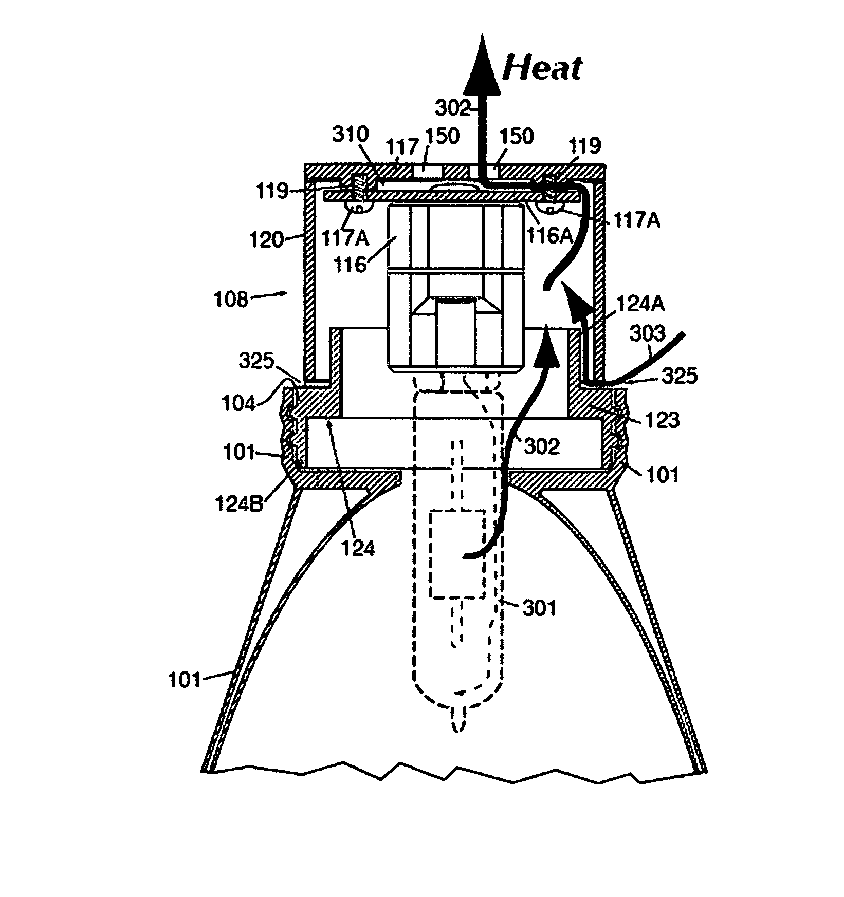
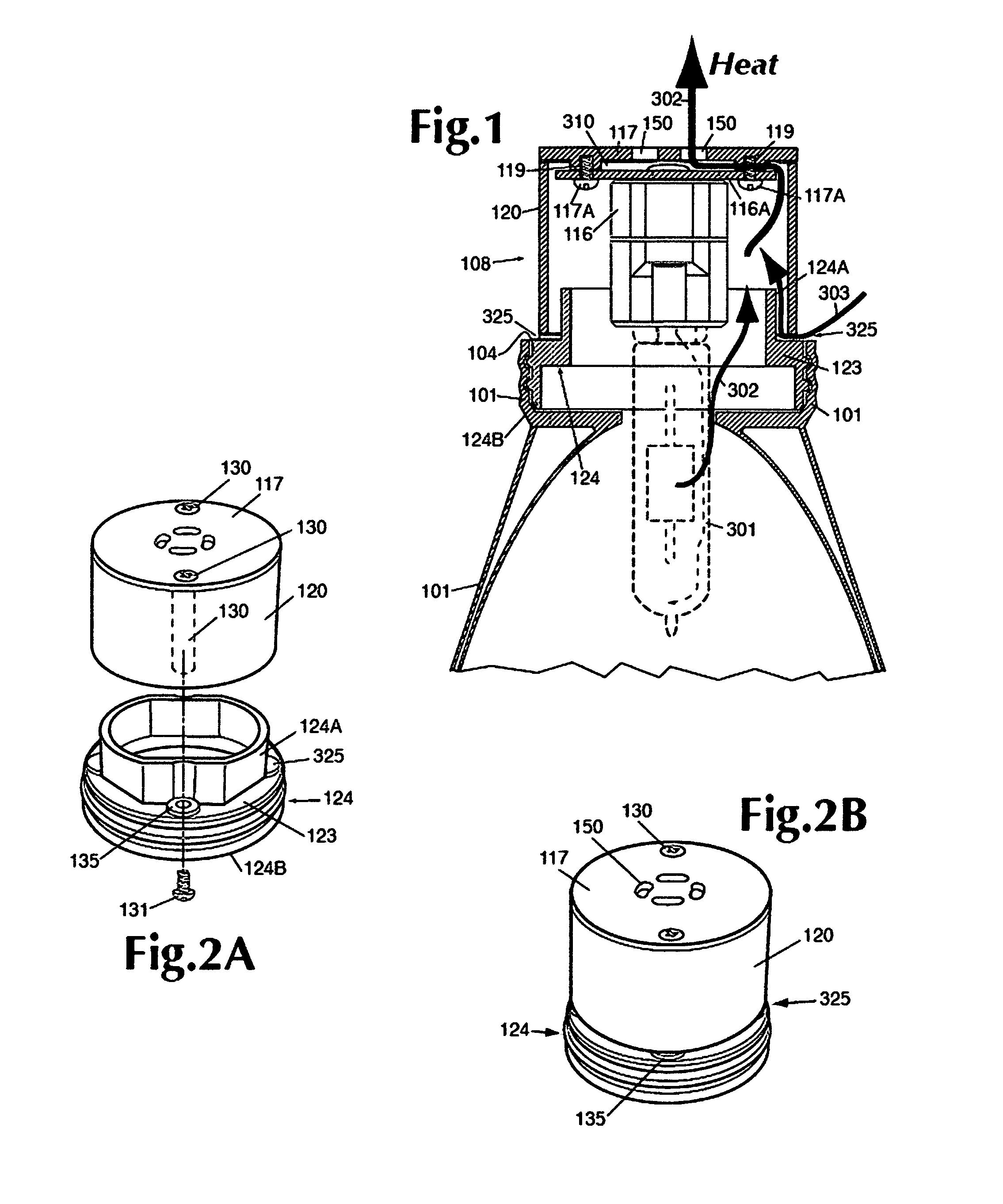
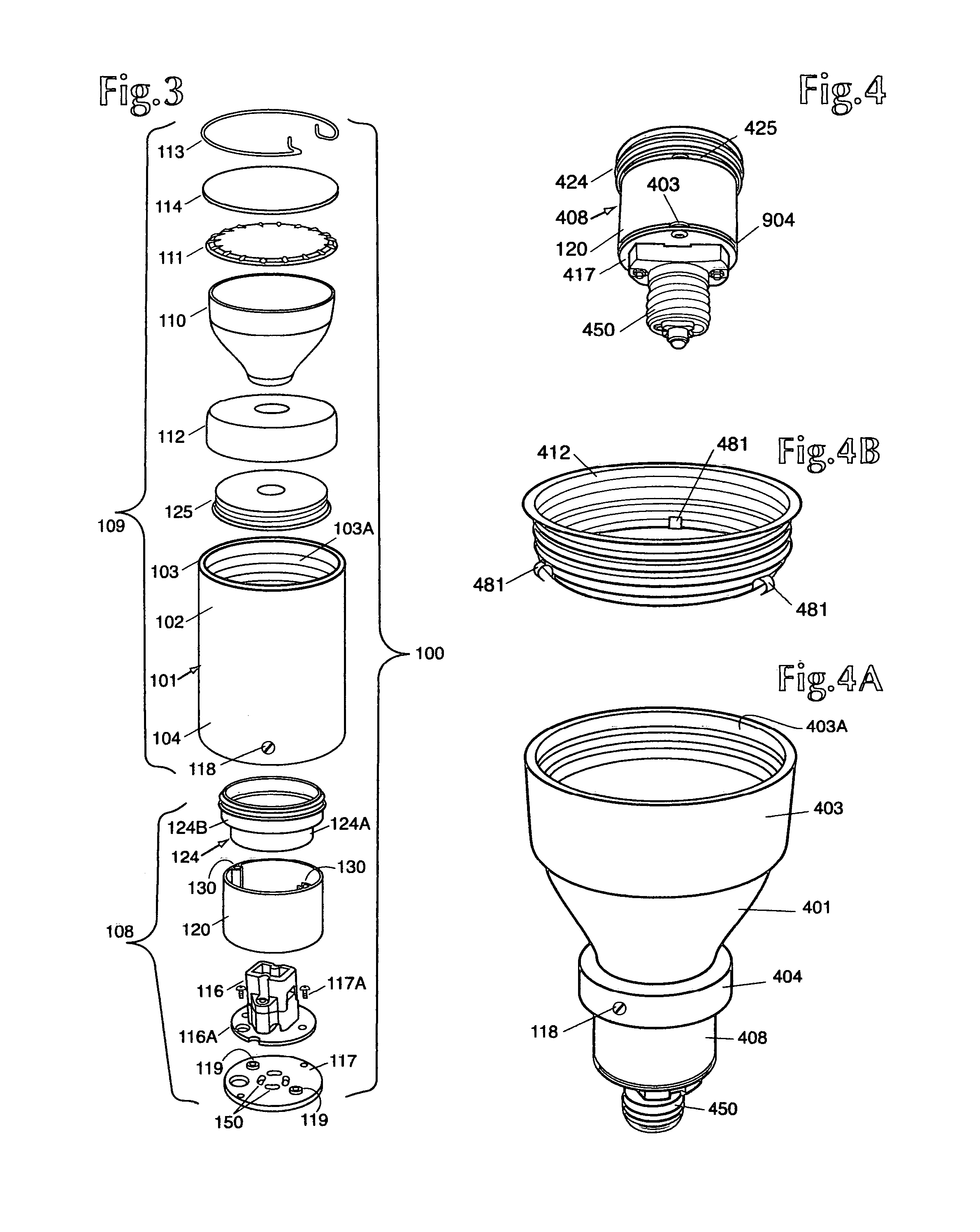
[0044]Referring now to FIG. 1, there is shown a cutaway view of an assembled socket cup assembly 108 which is shown exploded in FIG. 3. A representative lamp 301 is depicted in dashed outline. This lamp design is not be limitative of the inventive concept described herein.

[0045]The assembly 108 includes a lamp holder 116 of suitable construction for receiving a particular lamp. The specific design of the lamp holder 116 may vary as determined by the lamp 301 and the base configuration thereof.

[0046]A socket mounting plate 116A is attached to the end of the lamp holder 116 by any suitable means such as rivets, screws, adhesives or the like. The holder 116 and the plate 116A may be integrally formed in some instances.

[0047]The socket mounting plate 116A is attached to an end cap 117 by screws 117A or the like which are threadedly engaged with the standoffs 119. The standoffs 119 provide ventilation space 310 intermediate the plate 116A and the end cap 117 so that air can flow between ...


PUM


Abstract

The invention features an improved lighting fixture structure with temperature control and stray light reductions, together with a unique directional pivot/extension mounting mechanism.

Description

BACKGROUND OF THE INVENTION[0001]1. Field of the Invention[0002]This invention is directed to lighting fixtures, in general, and to lighting fixtures which provide reduction of temperature, reduction of unwanted glare from side light loss and, as well, can use directional extension mounting mechanisms while using CMH or similar lamps, in particular.[0003]2. Prior Art[0004]There are many light fixtures known in the art which can be classified into a number of categories such as track lighting, recessed down lights and the like. The broadest category is decorative fixtures, such as ceiling and surface mounted fixtures, wall mounted fixtures, pendant mounted fixtures and the like. Many of these fixtures permit replacement of conventional incandescent lamps.[0005]In addition, there are many types of reflective glass covers known in the art. These covers typically include an aluminized glass reflector, support necks attached thereto, and appropriate threaded collars for mounting the refl...

Claims


Application Information

Patent Timeline
Patent Type & Authority Patents(United States)
IPC IPC(8): F21V29/00
CPCF21V13/04F21V17/06F21V19/0065F21V29/83F21V29/004F21V21/04F21V21/35F21W2131/40F21V21/30
Inventor AUBREY, TRUMAN
Owner AUBREY TRUMAN
Why Eureka
Try Eureka