Scalpel blade guard

a blade guard and blade technology, applied in the field of blade guards, can solve the problems of placing limitations on the use of scalpels and the ability to move only limited distances from blade edges, and achieve the effect of preventing injuries

Inactive Publication Date: 2009-02-03
NEW YORK UNIV
View PDF10 Cites 17 Cited by
  • Summary
  • Abstract
  • Description
  • Claims
  • Application Information

AI Technical Summary

Benefits of technology

[0004]The present invention provides an improved scalpel shield system for a scalpel that has a handle and a blade with a sharp cutting edge, the system comprising an adapter mountable on the scalpel and provided with a first pivot component; and a blade guard member having a second pivot component engagable with the first pivot component and manually pivotable relative to the adapter between a guard position for preventing injury by the sharp cutting edge and a retracted position for exposing the sharp cutting edge.

Problems solved by technology

The known devices are generally capable of only limited movement away from the blade edge, thus placing certain limitations on the use of the scalpel.

Method used


Image

  • Scalpel blade guard
  • Scalpel blade guard
  • Scalpel blade guard

Examples


third embodiment

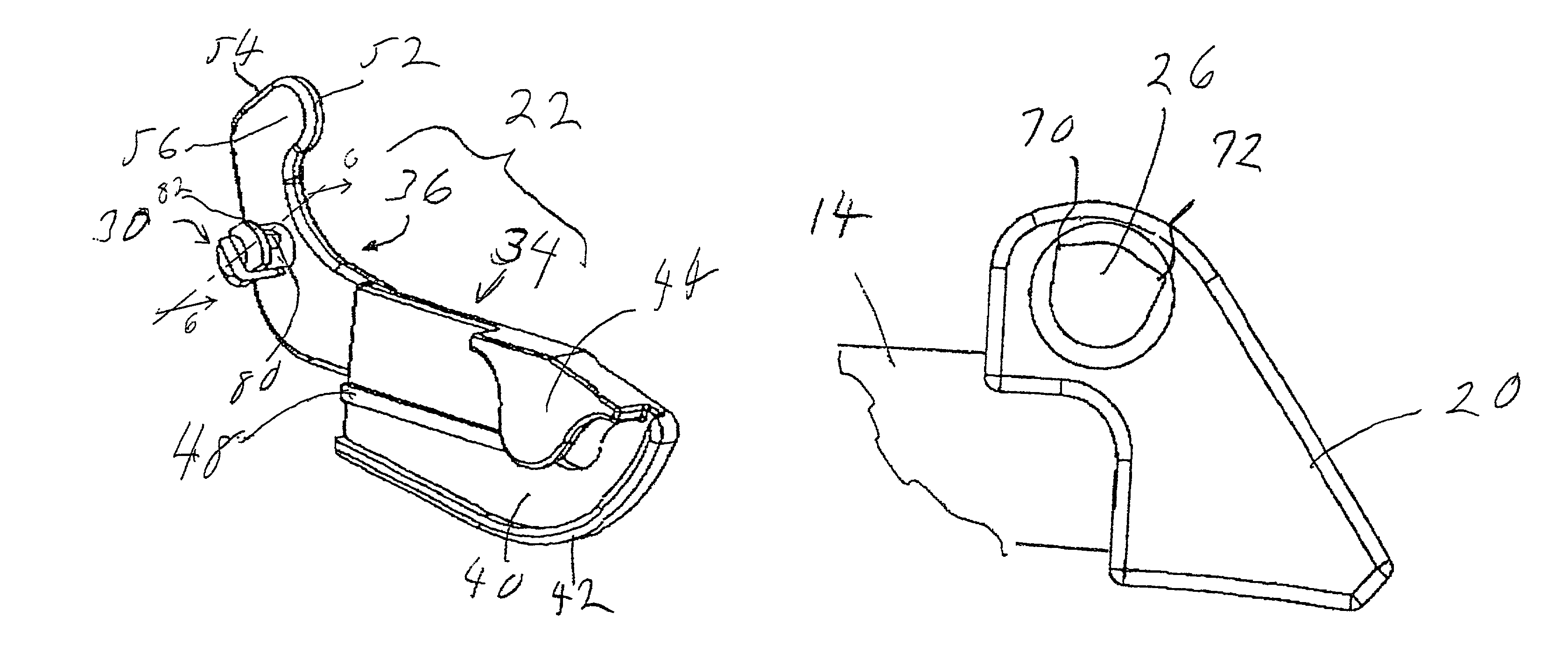
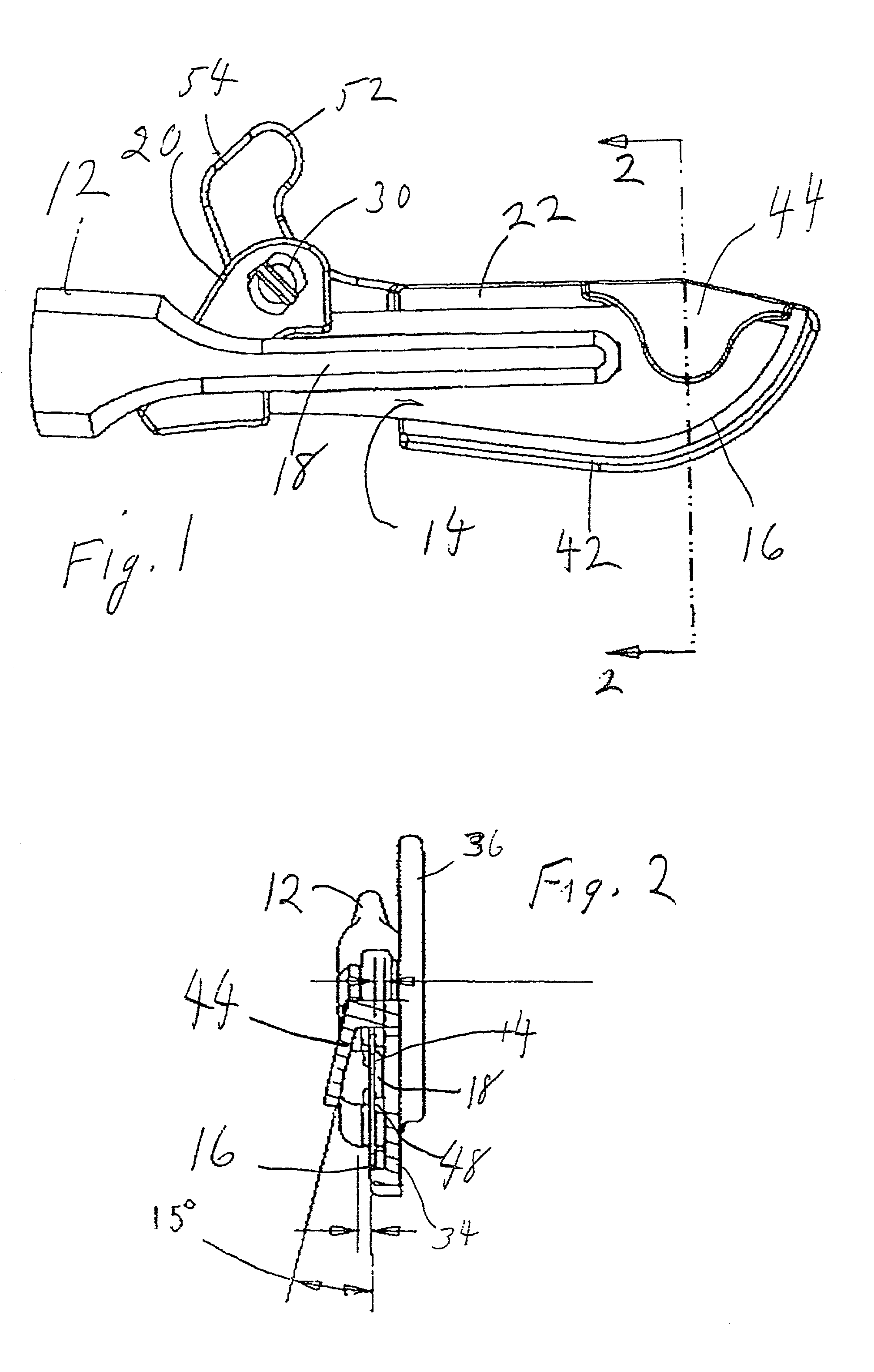
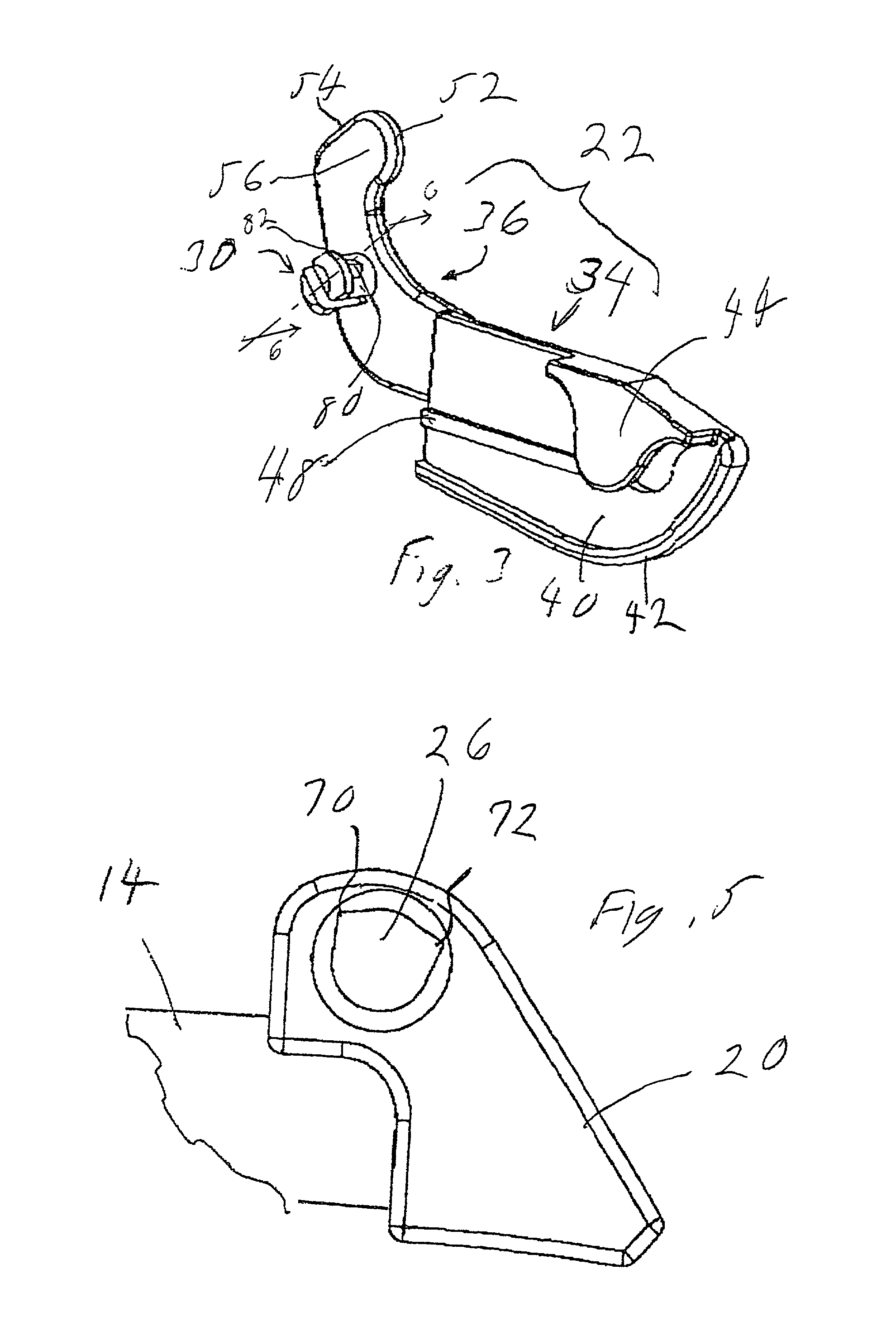
[0025]The surface of wall 40 that faces blade 14 carries a longitudinally extending, laterally projecting rib 48. As best seen in FIG. 2, blade supporting member 18 and rib 48 cooperate to retain guard member 22 in the guard position. When member 22 is in this position, rib 48 is located directly below a portion of blade supporting member 18 that projects from blade 14 toward side wall 40. Such a portion of blade supporting member 18 is shown in FIGS. 2 and, as element 124, in FIGS. 10-12, which illustrate the invention. When guard member 22 is pivoted away from the guard position, counterclockwise in FIG. 1, rib 48 is deflected laterally by supporting member 18 to prevent guard member 22 from ever touching cutting edge 16.

[0026]Control portion 36 is fixed to cover portion 34 and the two portions 34 and 36 are preferably formed as a unitary molded component. Each basic part 20, 22 of the blade guard system is preferably a molded plastic, the preferred material being polypropylene or...

first embodiment

[0046]Guard member 102 is further provided with control elements 140 having operating surfaces that, like surface regions 52 and 54 of the first embodiment, can be manually engaged by the user's finger to move guard member 102 between its guard position and its retracted position, while the user continues to grasp handle 104.

[0047]A fourth embodiment of the invention is illustrated in FIGS. 17-20. It will be noted that this embodiment is generally similar to the first embodiment illustrated in FIGS. 1-5. Therefore, many of the structural features of the fourth embodiment that are identical to those of the first embodiment will not be provided with reference numerals in FIGS. 17-20.

fourth embodiment

[0048]The fourth embodiment is composed essentially of an adapter 20′ (FIGS. 18 and 20), a blade guard member 22′ (FIG. 17) and a biasing spring 24.

[0049]The fourth embodiment differs from the first embodiment essentially in that the through hole 26′ of adapter 20′ and the outer surface of pin 30′ on guard member 22′ are essentially circular. Thus, pin 30′ is not provided with a rib, such as rib 80 of the first embodiment, but is provided with a rim 82 that serves to retain pin 30′ in place in hole 26′. As in the first embodiment, pin 30 is slotted along a plane containing the longitudinal axis the pin.

[0050]Adapter 20′ is provided with a circularly cylindrical sleeve 202, the outer edge of which will bear against rim 82 when member 22′ is assembled to adapter 20′. Therefore, pin 30 is made longer than pin 30 of the first embodiment by an amount equal to the height of sleeve 202.

[0051]The fourth embodiment is further provided with a biasing element, which is here in the form of a to...


PUM


Abstract

A scalpel shield system for a scalpel that has a handle and a blade with a sharp cutting edge. The system is mountable on the scalpel and provided with a blade guard member having a pivot component engagable with a pivot component on the blade or the handle. The blade guard member is manually pivotable relative to the scalpel between a guard position for preventing injury by the sharp cutting edge and a retracted position for exposing the sharp cutting edge.

Description

[0001]This application claims the benefit of U.S. provisional application 60 / 289,518 filed May 9, 2001.BACKGROUND OF THE INVENTION[0002]The present invention relates to scalpels, and particularly to arrangements for preventing accidental contact with the cutting edge of the scalpel blade.[0003]A variety of devices of this type, known generally as blade guards, are already known in the art. For example, devices of this type are disclosed in U.S. Pat. Nos. 5,676,677 and 5,843,107, as well as in a number of other issued patents. The known devices are generally capable of only limited movement away from the blade edge, thus placing certain limitations on the use of the scalpel.BRIEF SUMMARY OF THE INVENTION[0004]The present invention provides an improved scalpel shield system for a scalpel that has a handle and a blade with a sharp cutting edge, the system comprising an adapter mountable on the scalpel and provided with a first pivot component; and a blade guard member having a second p...

Claims


Application Information

Patent Timeline
Patent Type & Authority Patents(United States)
IPC IPC(8): A61B17/32B26B29/02
CPCA61B17/3213B26B29/02A61B2017/32113
Inventor ADELMAN, MARKLANDIS, ROBERTHIDALGO, CRAIG
Owner NEW YORK UNIV
Why Eureka
Try Eureka