Total disc replacement system and related methods

a total disc and disc replacement technology, applied in the field of spinal surgery, can solve the problems over-distraction of vertebral endplates, anchor plates dislocated from vertebral end plates, etc., and achieve the effect of reducing the overall profile of total disc replacement system

Active Publication Date: 2009-02-03
NUVASIVE
View PDF12 Cites 74 Cited by
  • Summary
  • Abstract
  • Description
  • Claims
  • Application Information

AI Technical Summary

Benefits of technology

[0009]The semi-cylindrical surface of the first and / or second anchor plates and the first and / or second intradiscal liners may be generally concave and / or generally convex. The generally arcuate cross-sections of the first and / or second articular surfaces of the intradiscal element may be generally concave and / or convex. The second surface of the first and / or second anchor plates may include a ramped portion to facilitate the introduction of the intradiscal element into articulating engagement with the semi-cylindrical articular surfaces of the first and second anchor plates. The intradiscal element may be prevented from translating relative to the first and / or second anchor plates.
[0017]The semi-cylindrical articular surfaces of the first and / or second pairs of intradiscal liners and the first and / or second intradiscal pivots may be generally concave and / or generally convex. The second surface of the first and / or second anchor plates may include a ramped portion to facilitate the introduction of the intradiscal element into articulating engagement with the semi-cylindrical articular surfaces of the first and second pairs of intradiscal liners. The intradiscal element may be prevented from translating relative to the first and / or second anchor plates by any suitable method, such as (by way of example only) by including one or more obstructions along the first and / or second intradiscal liners and / or cutout regions or by the introduction of a suitable adhesive substance.
[0019]The intradiscal element may take any number of different forms. In one aspect, the intradiscal element may be provided as a single generally spherical member or at least two semi-spherical members coupled together. In another aspect, intradiscal element may include at least one generally semi-cylindrical articular surface for articulating with the semi-cylindrical articular surface of the first and / or second pair of intradiscal liners. In this embodiment, the intradiscal element may be provided as a unitary member and / or may comprise a first intradiscal pivot rotatably coupled to a second intradiscal pivot via (by way of example only) a post. In yet another aspect, the intradiscal element may include a pair of opposing generally planar surfaces in order to reduce the overall profile of the total disc replacement system of the present invention.

Problems solved by technology

Known total disc replacement systems suffer disadvantages including the dislocation of the anchor plates from the vertebral end plates, over-distraction of the vertebral endplates during introduction, particulate wear and debris of the component parts, and a lack of conformity between the anchor plates and the internal components during use.

Method used


Image

  • Total disc replacement system and related methods
  • Total disc replacement system and related methods
  • Total disc replacement system and related methods

Examples


first embodiment

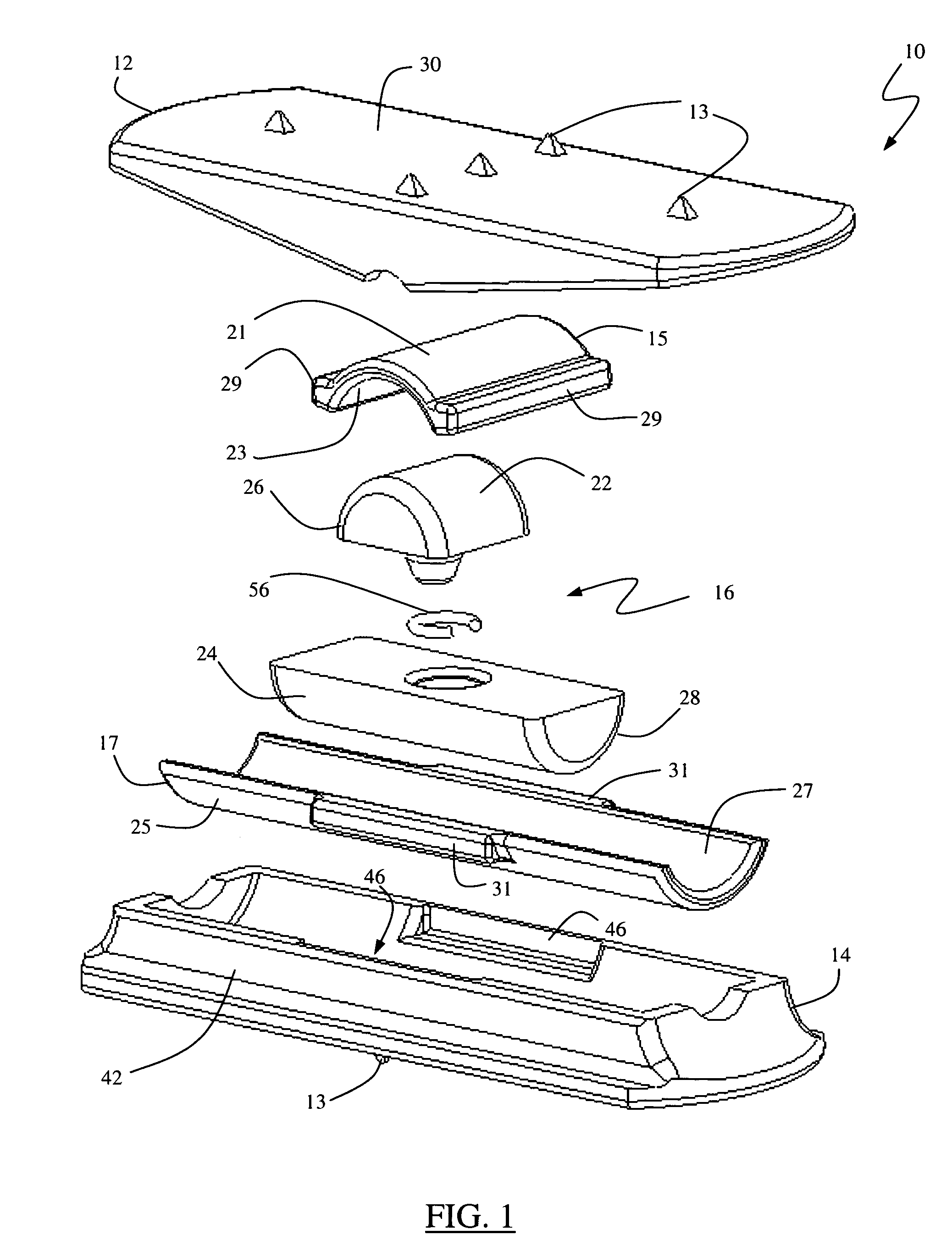
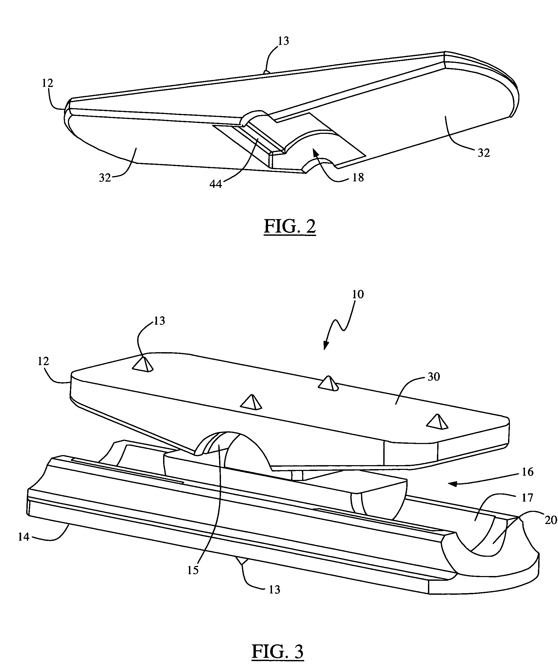
[0050]FIGS. 1-5 illustrate a total disc replacement (TDR) system 10 according to the present invention. The TDR system 10 includes a first anchor plate 12, a second anchor plate 14, a pair of intradiscal troughs or liners 15, 17, and an intradiscal element 16. Each anchor plate 12 and 14 is equipped with a plurality of anchor elements 13 and a semi-cylindrical surface 18, 20, respectively. The first intradiscal liner 15 includes a first surface 21 and a second surface 23, each having a generally arcuate cross-section. The first surface 21 is dimensioned to fit into the semi-cylindrical surface 18 of the first anchor plate 12, allowing the first intradiscal liner 15 to form a protective barrier between intradiscal element 16 and first anchor plate 12, thereby reducing wear. The second intradiscal liner 17 includes a first surface 25 and a second surface 27, each having a generally arcuate cross-section. The first surface 25 is dimensioned to fit into the semi-cylindrical surface 20 o...

second embodiment

[0069]FIG. 13 illustrates a total disc replacement (TDR) system 110 according to the present invention. The TDR system 110 is designed to operate in the same fashion as the TDR system 10 shown and described above, except that the TDR system 110 is particularly suited for anterior access introduction into the spine. (For the sake of clarity, all features or components in common with the TDR system 10 will be numbered identically to those features, all features similar in function but different in form will be numbered +100, and reference can be made to the discussion above regarding the TDR system 10, rendering a repeat discussion unnecessary and optional). The central distinction between TDR system 10 and TDR system 110 is that the first and second anchor plates 112, 114 each have a generally cylindrical shape. Dimensioning the first and second anchor plates 112, 114 in this fashion is advantageous when a minimal access surgical corridor is not required. Related to the generally cyl...

third embodiment

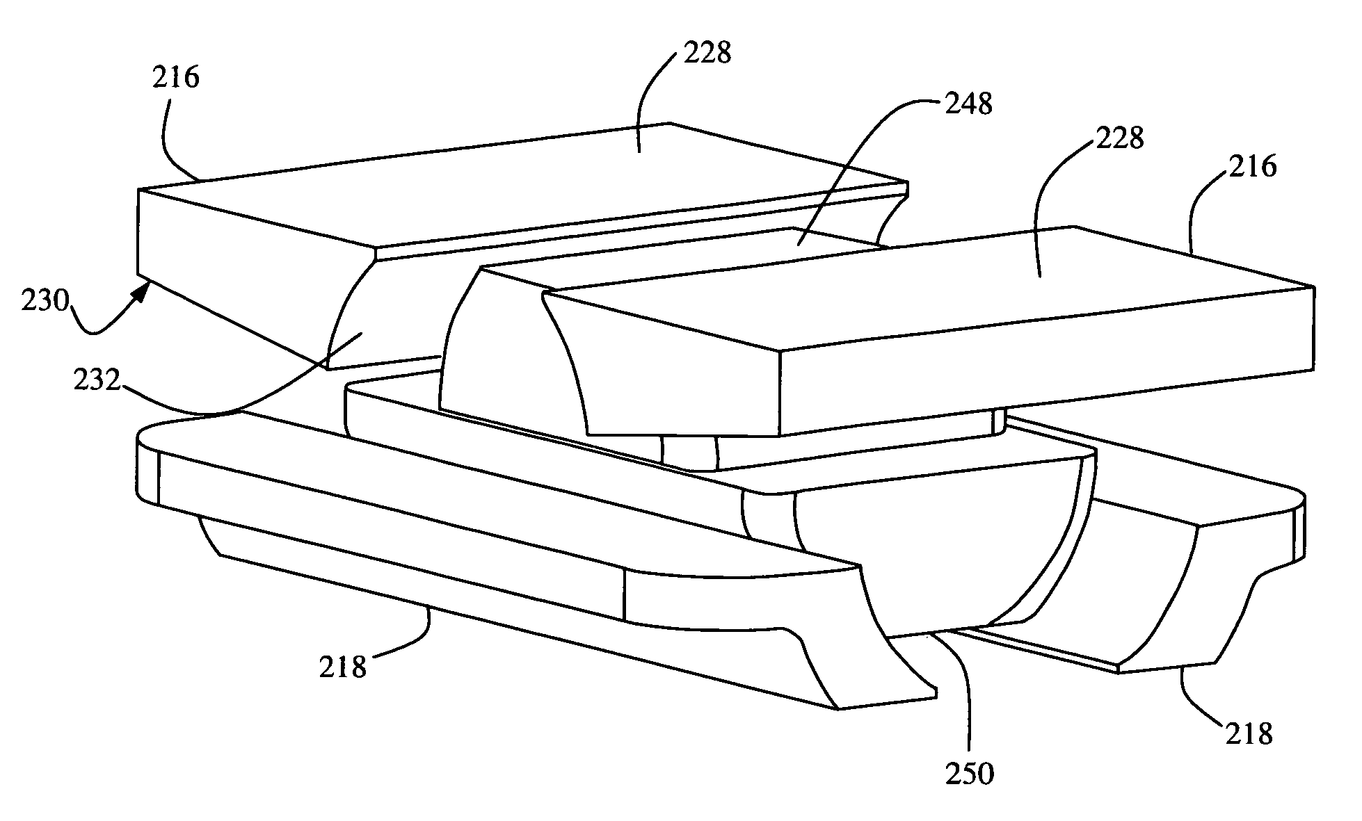
[0070]FIGS. 14-18 illustrate a total disc replacement (TDR) system 210 according to the present invention. The TDR system 210 includes a first anchor plate 212, a second anchor plate 214, a first pair of intradiscal liners 216, a second pair of intradiscal liners 218, and an intradiscal element 220. Each anchor plate 212, 214 is equipped with a plurality of anchor elements 222 and a cutout region 224, 226, respectively. The first pair of intradiscal liners 216 each have a first surface 228 dimensioned to fit into the cut-out region 224 of the first anchor plate 212, a second generally planar surface 230, and a semi-cylindrical articular surface 232 dimensioned to articulate with the intradiscal element 220. The second pair of intradiscal liners 218 each have a first surface 234 dimensioned to fit into the cut-out region 226 of the second anchor plate 214, a second generally planar surface 236, and a semi-cylindrical articular surface 238 dimensioned to articulate with the intradisca...


PUM


Abstract

A total disc replacement (TDR) system for use in the spine and related methods, involving a first anchor plate having a first surface for engaging a first vertebra and a second surface including a semi-cylindrical surface, a second anchor plate having a first surface for engaging a second vertebra and a second surface including a semi-cylindrical surface, a pair of intradiscal liners, each having a first semi-cylindrical surface for engaging with said anchor plates and a second semi-cylindrical surface for engaging with an intradiscal element, and an intradiscal element including a first articular surface having a generally arcuate cross-section for articulating with said first intradiscal liner, and a second articular surface having a generally arcuate cross-section for articulating with said second intradiscal liner.

Description

CROSS REFERENCES TO RELATED APPLICATIONS[0001]The present application is a nonprovisional patent application claiming benefit under 35 U.S.C. § 119(e) from U.S. Provisional Application Ser. No. 60 / 551,621, filed on Mar. 8, 2004, and U.S. Provisional Application Ser. No. 60 / 571,551, filed on May 13, 2004, the entire contents of which are hereby expressly incorporated by reference into this disclosure as if set forth fully herein.BACKGROUND OF THE INVENTION[0002]I. Field of the Invention[0003]The present invention relates generally to spinal surgery and, more particularly, to total disc replacement systems and related methods.[0004]II. Discussion of the Prior Art[0005]In recent years, the area of total disc replacement has experienced proliferated growth and attention from the medical community. Known total disc replacement devices generally require some form of articulation or inherent flexibility in the device to permit a spine having the device to maintain its natural posture and r...

Claims


Application Information

Patent Timeline
Patent Type & Authority Patents(United States)
IPC IPC(8): A61F2/44
CPCA61F2/4425A61F2/4611A61F2002/30224A61F2002/30364A61F2002/30398A61F2002/30448A61F2002/30495A61F2002/30604A61F2002/30841A61F2002/443A61F2220/0025A61F2220/0033A61F2220/005A61F2230/0069
Inventor CROOK, DAVIDCORNWALL, G. BRYAN
Owner NUVASIVE
Why Eureka
Try Eureka