
Steering column switch

a technology of steering column switch and switch, which is applied in the direction of contact mechanism, contact operating parts, transportation and packaging, etc., can solve the problems of relative complexity of design, and achieve the effect of simple and economical design

Inactive Publication Date: 2009-02-03
DELPHI TECH INC
View PDF10 Cites 10 Cited by
  • Summary
  • Abstract
  • Description
  • Claims
  • Application Information

AI Technical Summary

Benefits of technology

The invention is a steering column switch that uses a simple and economical design. The switch lever supports a rotary switch and magnetic-field sensors to determine the switch positions. The switch lever can have a push-button switch or a rotary switch, and the position of the signal transmitter is determined by the switch position of the switch lever and the push-button switch. The signal transmitter is a permanent magnet with a cylindrical cross section, and the magnetic-field sensors detect signals of the magnet. The invention allows for contact-less switching and simplifies the construction of the switch.

Problems solved by technology

This switch is disadvantageous in the respect that it has a relatively complicated design.

Method used


Image

  • Steering column switch
  • Steering column switch

Examples


Embodiment Construction

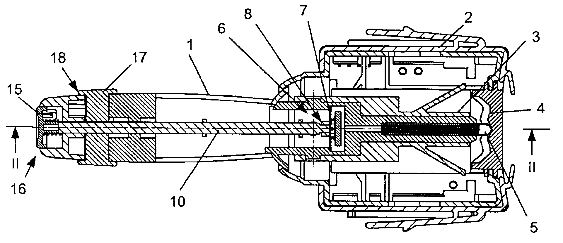
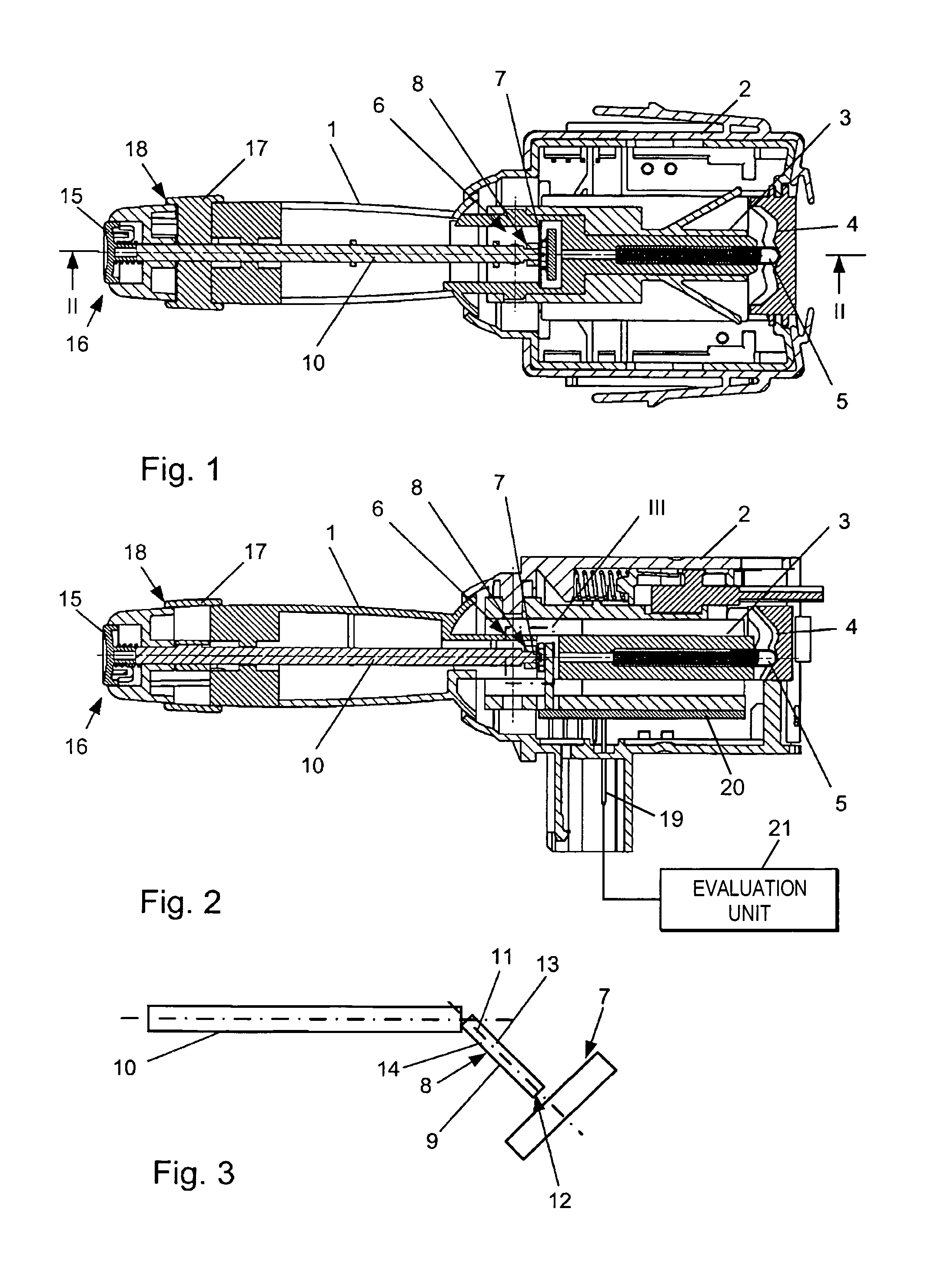
[0018]The steering column switch comprises a switch lever 1, which is inserted into a foot 3 supported in a housing 2. The foot 3 of the switch lever 1 that can pivot transversely has, on its free end, a locking sleeve 5 interacting with a locking cam 4. In the coupling region of the foot 3 with the switch lever 1 there is a free space 6, in which there is a sensor array 7 containing at least two magnetic-field sensors and a magnetic signal transmitter 8, which interacts with these sensors and which is constructed as a permanent magnet 9. The cylindrical permanent magnet 9 is fixed to one end of a switch shaft 10 supported in the switch lever 1, such that its longitudinal axis 11 is not parallel to the switch shaft 10 and its free end face 12 is aligned relative to the sensor array 7. The dipolar permanent magnet 9 has poles of different sign along its longitudinal halves 13, 14. The switch shaft 10 is connected, with its end opposite the permanent magnet 9, to an activation element...


PUM


Abstract

A steering column switch, especially for a motor vehicle, contains a switch lever, which is activated transversely and which has a magnetic signal transmitter, to which several stationary magnetic-field sensors coupled to an evaluation unit are allocated for determining the switch positions of the switch lever. The switch lever supports a rotary switch and the signal transmitter and also the magnetic-field sensors are used for determining the switch positions of the rotary switch.

Description

TECHNICAL FIELD[0001]The invention relates to a steering column switch, especially for a motor vehicle, with a switch lever, which is activated transversely and which has a magnetic signal transmitter, to which several stationary magnetic-field sensors coupled to an evaluation unit are allocated for determining the switch positions of the switch lever.BACKGROUND OF THE INVENTION[0002]DE 299 01 614 U1discloses an electric switch for contact-less switching with a movable switch lever, to which is allocated a switching arm which has a magnetosensitive switch-position detection device and which is guided in a switch tack to produce a switching feel in each of the individual switch positions that is characterized by a perceptible engagement. The switch position detection device includes a magnetic signal transmitter coupled to the switch movement of the switching arm and a converter arrangement, which is stationary relative to the movement of the magnetic signal transmitter and which is ...

Claims


Application Information

Patent Timeline
Patent Type & Authority Patents(United States)
IPC IPC(8): H01H9/00
CPCB60Q1/1476
Inventor REISCHL, ERIKLENG, PETERSCHNELL, KLAUSKOEHLER, JOACHIM
Owner DELPHI TECH INC
Learn More