Wheel suspension

a technology of suspension and wheel, applied in the direction of resilient suspension, interconnection system, vehicle components, etc., can solve the problems of comparatively complex electric motor drive, comparatively oversensitive steering, unpleasant experience for users,

Inactive Publication Date: 2013-09-17
FORD GLOBAL TECH LLC
View PDF15 Cites 1 Cited by
  • Summary
  • Abstract
  • Description
  • Claims
  • Application Information

AI Technical Summary

Benefits of technology

[0004]It is the underlying object of the invention to create a wheel suspension with a flexible and adaptable tie rod springiness or compliance, the design and production of which tie rod are simple and economical.
[0010]As already stated, the first rod part has the cylindrical compensating space open at one end. To seal off said space relative to the surroundings, provision is advantageously made to form a cap-type cover with a central opening and two contact lips spaced apart in the vertical direction when viewed in longitudinal section. In this way, a receiving space is formed between an inner contact lip and an outer contact lip, said receiving space being matched to the wall thickness of the receiving space, thus enabling the cap-type cover simply to be placed on the open end in a manner which is sufficiently leaktight and secure in terms of position. It is, of course, also possible for the cap-type cover to be screwed on, for which purpose it is, of course, possible to provide corresponding threads. In a preferred embodiment, provision can be made for the inner contact lip to be made longer when viewed in longitudinal section than the outer contact lip. The inner contact lip serves inter alia as a guide for the piston rod, with a longer length improving guidance—The length of the outer contact lip, on the other hand, can be designed for adequately firm seating of the cap-type cover.
[0016]The invention offers the advantage that the wheel suspension can be of particularly simple and economical design and that, by virtue of the variation in the length of the tie rod, it is also possible to vary the springiness or compliance in order to adapt to the different conditions at different speeds. This allows a wheel suspension which has sufficient accuracy and good response behavior at low vehicle speeds but, at the same time, does not respond in an excessively unstable and oversensitive manner at high vehicle speeds. Moreover, the wheel suspension is simple and economical to manufacture, and this is likewise advantageous.
[0018]The medium reservoir is advantageously pressurized by means of the pressurization element. This can preferably be achieved by providing the spring-loaded pressure plate in the medium reservoir, said plate tending to push the compensating medium back into the compensating space. By means of the interaction between the medium reservoir, the compensating space, the pressurization and the valve, the adjustable springiness or compliance of the tie rod can be set to match the application, preferably according to the differing speeds of the vehicle. However, the design is simple and effective in all cases.

Problems solved by technology

However, this results in excessive responsiveness in the steering at high vehicle speeds, making the steering comparatively oversensitive, which is an unpleasant experience for the user.
The disadvantage here is that this electric motor drive is comparatively complex and that a control system is additionally required for this purpose.

Method used


Image

  • Wheel suspension
  • Wheel suspension

Examples


Embodiment Construction

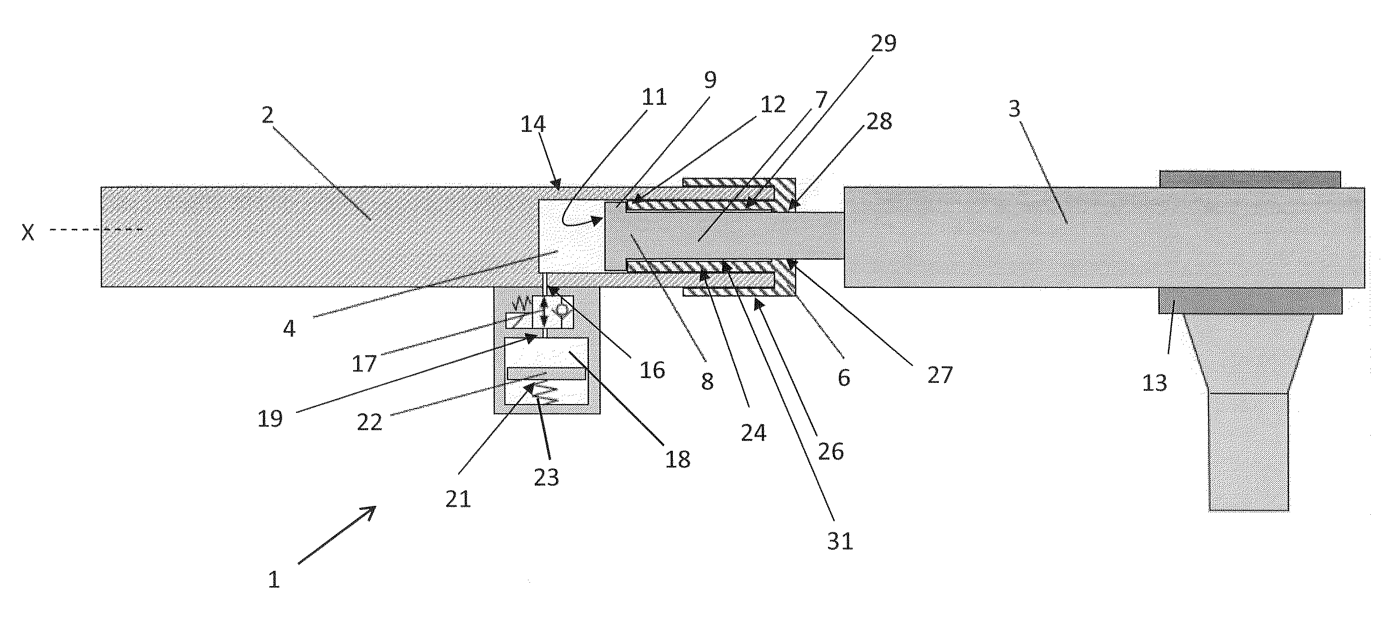
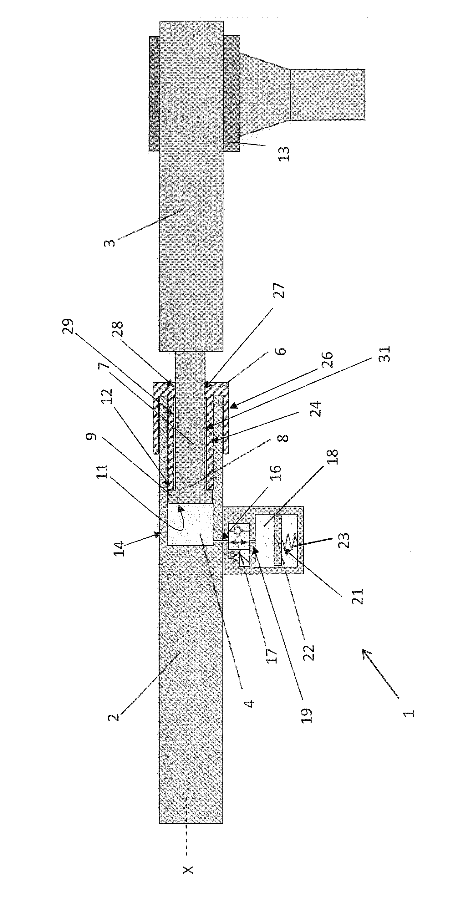
[0024]FIG. 1 shows a tie rod 1 of a wheel suspension. The wheel suspension itself is not shown. The operation and attachment of the tie rod 1 is known, for which reason no details thereof will be given here.

[0025]The tie rod 1 is formed by two rod parts 2 and 3. The rod part on the left in the plane of the drawing, i.e. the first rod part 2, has a compensating space 4, which is of cylindrical design when viewed in longitudinal section and is open at one end, e.g. toward the right-hand plane of the drawing.

[0026]The compensating space 4 is filled with a compensating medium, preferably a fluid, more preferably a hydraulic oil. To seal off the compensating space 4, a cap-type cover 6 is provided, said cover being described in greater detail below.

[0027]The engagement end 7 of the other, i.e. second, rod part 3, which is on the right in the plane of the drawing, passes through the cap-type cover 6 and reaches into the compensating space 4.

[0028]By way of example, the engagement end 7 ha...


PUM


Abstract

The invention relates to a wheel suspension for a motor vehicle, which has a tie rod (1) formed from two rod parts (2, 3). In order to achieve speed-dependent adaptation of the compliance of the tie rod, the proposal is that the first rod part (2) have a compensating space (4) filled with a compensating medium, in which the other, second rod part (3) is arranged by means of the engagement end (7) thereof, the compensating space (4) being connected to a, preferably pressurized, medium reservoir (18) via a switching element (17) arranged at a connecting element (19).

Description

BACKGROUND OF THE INVENTION[0001]The invention relates to a wheel suspension for a motor vehicle of the type stated in the preamble of claim 1, the wheel suspension having a tie rod formed from two rod parts. Wheel suspensions of this kind are used in motor vehicles, e.g. at the driven axle.[0002]In designing such wheel suspensions, a number of aspects have to be taken into account. On the one hand, there is a demand that the steering feel should be very precise at low and moderate vehicle speeds. Relatively stiff tie rods and thrust rods with little springiness or compliance are required for this purpose. However, this results in excessive responsiveness in the steering at high vehicle speeds, making the steering comparatively oversensitive, which is an unpleasant experience for the user. It is therefore better at high vehicle speeds if the tie rod is more flexible and the thrust rod has a greater springiness or compliance. An ideal wheel suspension then falls within a range betwee...

Claims


Application Information

Patent Timeline
Patent Type & Authority Patents(United States)
IPC IPC(8): B60G21/045
CPCB60G7/003B62D7/20B62D17/00B60G2206/1116
Inventor HINTZEN, RALF
Owner FORD GLOBAL TECH LLC
Why Eureka
Try Eureka