Barrel-type fish/particle screen with adjustable flow distribution and debris removal

a filter screen and filter screen technology, applied in the field of filter screen, can solve the problems of inflow non-uniformity, and achieve the effects of reducing or avoiding harm to aquatic life, reducing air pollution, and reducing water pollution

Inactive Publication Date: 2014-02-04
WINTHER JOHN L +1
View PDF13 Cites 6 Cited by
  • Summary
  • Abstract
  • Description
  • Claims
  • Application Information

AI Technical Summary

Benefits of technology

[0006]One of the discoveries forming the basis of the present invention is that one site of nonuniformity of water inflow along the length of the cylinder axis is at the narrow end of the conical collection manifold, i.e., the end opposite the location of the water intake vessel through which the water leaves the fish screen. With the manifold typically closed off at this end, the water within the collection manifold at this end is at relatively high pressure and therefore has a reduced velocity head, causing a reduced flow rate into the collection header at this end. In one aspect of this invention, this localized reduction in flow is addressed by placing a valve over this narrow end rather than permanently closing it off, the valve allowing the narrow end to vary between being closed off entirely and being open to allow an axial inflow of water at that end, rather than only a radial inflow through the sides of the manifold. The position of the valve can thus be adjusted to provide optimal flow for any of a range of conditions, and thereby to accommodate for example differences in ambient conditions and differences in the rate at which water is being drawn through the collection manifold by the intake vessel.
[0007]In another aspect of this invention, the need to maintain the cylindrical screen clear of debris while minimizing or avoiding harm to the aquatic life surrounding the screen is addressed by the placement of perforated air pipes between the cylindrical screen and the conical collection manifold, and particularly near the inner surface of the screen, the pipes having holes that are oriented such that the axes of the holes form an acute angle with the radius of the screen and collection manifold. When pressurized air is fed through the pipes, therefore, the air jets emerging from the holes will strike the cylindrical screen at close proximity to the screen surface and at an acute angle rather than in a direction perpendicular to the surface. This non-perpendicular angle of impact causes air from the holes to be distributed across the entire surface of the screen, thereby covering a greater area of the screen before penetrating the screen to dislodge the debris on the outside surface. This provides better cleaning of the screen and uses less air. In addition, the air bursts will have a lesser impact on the surrounding water at the outer sides of the screen opposite the pipes than the impact created by direct radial jets and will also avoid or lessen the disruptive noise cause by air jets of the prior art. These effects will minimize trauma to aquatic life in the water adjacent to the screen.
[0008]In yet another aspect of this invention, the conventional open rib structure of barrel-type fish screens of the prior art is replaced by webs as rigid connecting members connecting the air pipes to the collection manifold, tapering along their lengths to match the taper of the collection manifold. The air pipes thereby serve as structural flanges or struts, and the webs provide structural support to the along the entire length of the fish screen. This allows for easy placement, removal, and replacement of the foraminous shell, while also allowing the entire fish screen to be made longer in relating to its diameter, i.e., a greater length / diameter ratio, without loss of structural integrity for the cylindrical shape of the shell.

Problems solved by technology

Inflow nonuniformity nevertheless remains a challenge.

Method used


Image

  • Barrel-type fish/particle screen with adjustable flow distribution and debris removal
  • Barrel-type fish/particle screen with adjustable flow distribution and debris removal
  • Barrel-type fish/particle screen with adjustable flow distribution and debris removal

Examples


Embodiment Construction

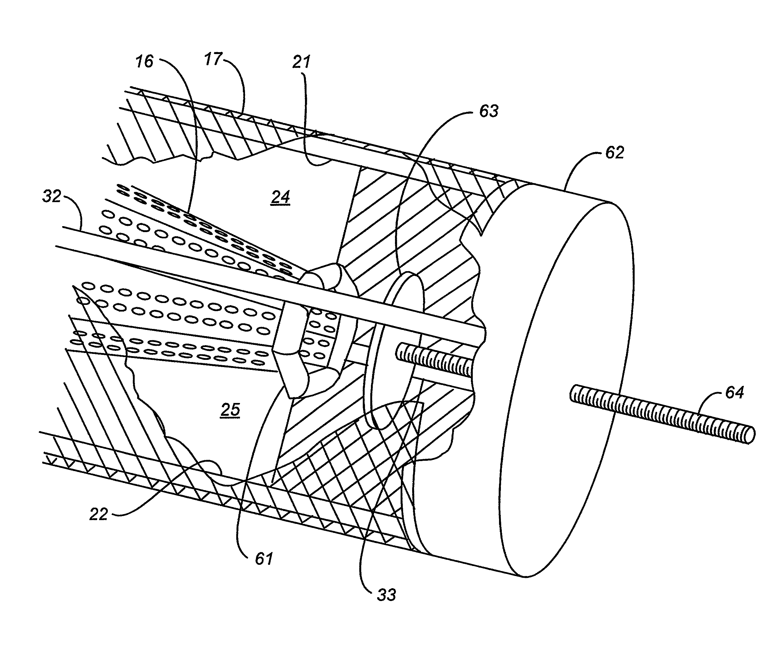
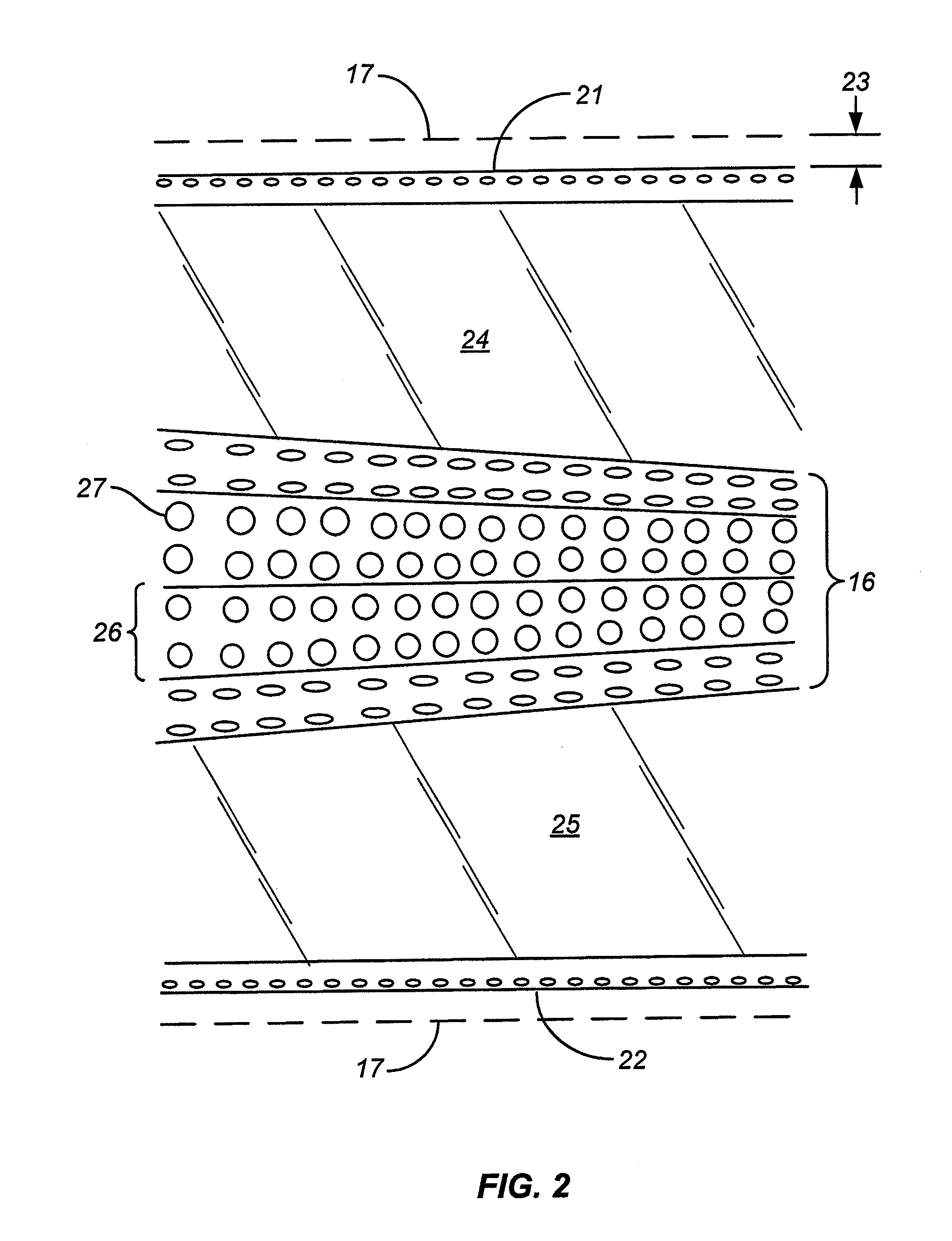
[0018]The cylindrical screen that forms the outer portion of the fish screens addressed herein is referred to herein as a foraminous cylindrical shell. The word “shell” denotes that the screen is the outermost component of the apparatus and surrounds the inner components including the collection manifold. The term “cylindrical” is used to denote that the shell is a lateral enclosure with a longitudinal axis and a substantially uniform cross section along the length of the axis. The term is intended to include enclosures whose cross section is a circle (circular cylinders) as well as those whose cross section is a closed curve other than a circle, such as an ellipse, and those whose cross section is a polygon, such as a hexagon or an octagon. In most implementations of this invention, the cylindrical shell will have a generally circular cross section. The term “foraminous” is used herein to denote a sheet that has openings distributed over its surface. Examples of foraminous material...


PUM

PropertyMeasurementUnit
acute angleaaaaaaaaaa
lengthaaaaaaaaaa

Abstract

Debris adhering to the outer surface of a barrel-type fish screen is cleared by air bursts from a series of perforated air pipes positioned inside the outer foraminous shell of the screen, the perforations being holes with axes at an acute angle to the screen radius for efficient use of the air. Separately, the conical water collection manifold mounted inside the shell is open at its narrow end, with a valve mounted to that open end to control the opening. The opening prevents reduced water inflow at that end of the manifold, and the valve adjusts the access of the surrounding water to the opening, thereby allowing the manifold to be tuned to more closely approach a uniform distribution of axial water flow along the length of the collection manifold for different ambient conditions. Webs joining the air pipes to the collection manifold are also included in certain embodiments of the invention to support increased lengths of the entire apparatus without loss of structural integrity, including support for the foraminous shell.

Description

BACKGROUND OF THE INVENTION[0001]1. Field of the Invention[0002]This invention relates to the transfer of water from bodies of water that are populated by live fish or particulate matter, or both. In particular, this invention addresses concerns encountered in the use of barrel-type fish screens that are designed to prevent fish and / or particulate matter from entering water intake vessels.[0003]2. Description of the Prior Art[0004]Water is often drawn from lakes, rivers, oceans, and other natural bodies of water for use by manufacturing plants, municipalities, irrigation systems, power plants, and other large operating facilities. Since these bodies of water typically support aquatic life that includes fish and other aquatic animals, screens commonly referred to as “fish screens” are commonly used to prevent the animals and particulate matter from entering the intake vessels through which the water is drawn and thus to prevent contamination and damage to units in the facilities such...

Claims


Application Information

Patent Timeline
Patent Type & Authority Patents(United States)
IPC IPC(8): B01D29/68E02B5/08B01D35/02B01D35/157E02B9/04B01D29/33
CPCB01D2201/02B01D29/58B01D29/33B01D2201/44B01D2201/084B01D35/02E03B3/04B01D35/1573B01D29/68E02B9/04E02B5/08Y02E10/20
Inventor WINTHER, JOHN L.TOLAND, BLAKE ANDREW
Owner WINTHER JOHN L
Why Eureka
Try Eureka