Arm for an unwinder and unwinder comprising said arm

a technology of unwinding arm and unwinding body, which is applied in the field of machine improvement, can solve the problems of long tailstock shaft, complex support system, expensive and bulky, etc., and achieve the effects of less stress, less bulky, and simple and more economical design

Active Publication Date: 2020-12-17
FOSBER
View PDF0 Cites 1 Cited by
  • Summary
  • Abstract
  • Description
  • Claims
  • Application Information

AI Technical Summary

Benefits of technology

[0009]In this way, the axial bulk of the system constituted by tailstock and brake is reduced. The supports of the tailstock shaft are less stressed, and are therefore simpler and more economical to design, as well as less bulky.

Problems solved by technology

The shaft of each tailstock is long and requires a complex support system.
Moreover, this known arrangement is complex, expensive and bulky.

Method used


Image

  • Arm for an unwinder and unwinder comprising said arm
  • Arm for an unwinder and unwinder comprising said arm
  • Arm for an unwinder and unwinder comprising said arm

Examples


Embodiment Construction

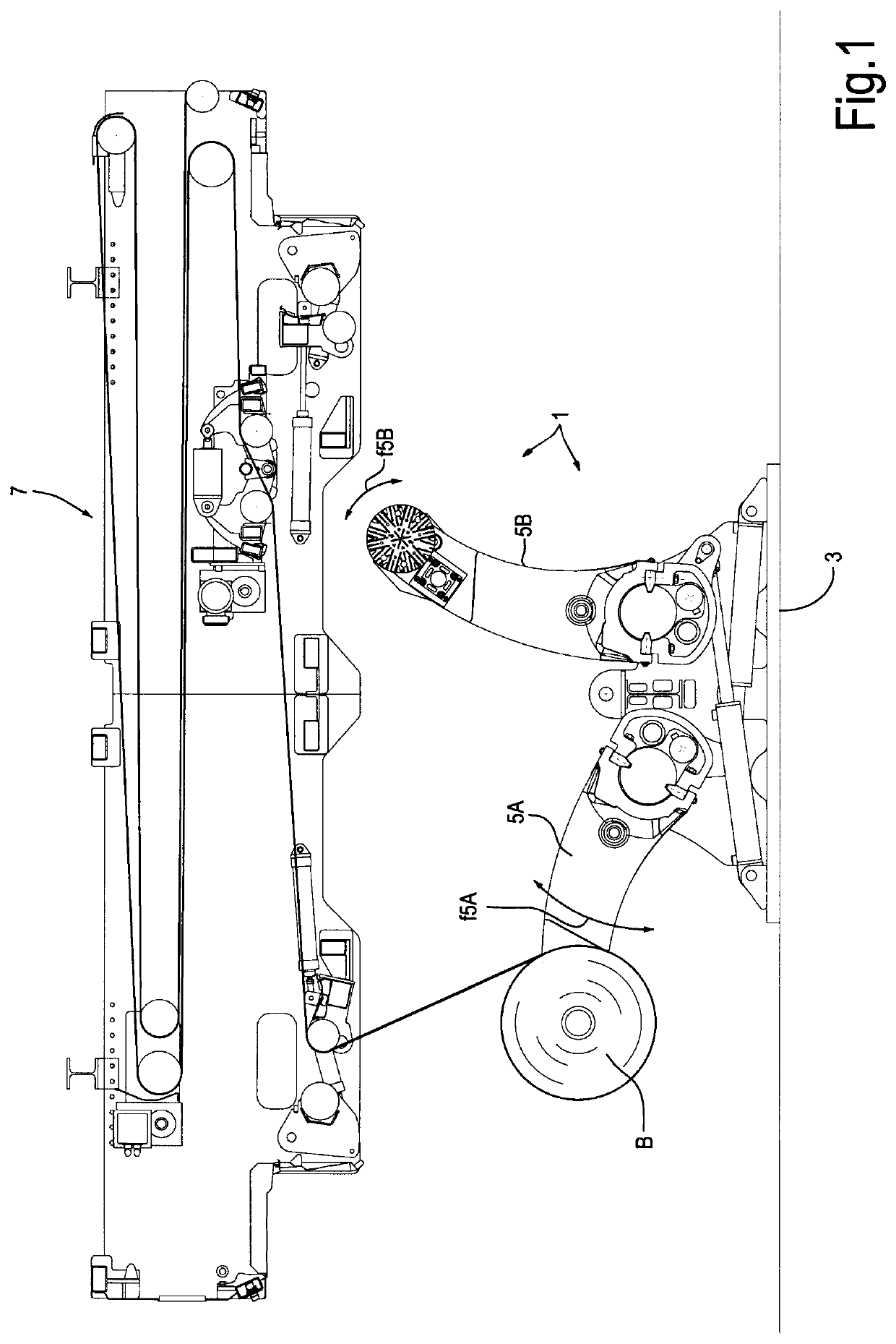
[0027]FIG. 1 schematically shows an unwinder 1 comprising a base or bearing structure 3, to which two pairs of arms 5 are hinged. FIG. 1 shows only one arm for each pair. Each pair of arms 5 is configured to support a roll B of paper or other web material that shall be unwound and fed to a converting line, not shown. A splicer 7 is provided above the arms 5 to join the tail edge of a roll supported by a pair of arms to the leading edge of a standing-by roll supported by the other pair of arms, so as continuously to feed the web material N to the converting line. The detailed features of the unwinder 1 and the splicer 7 are not relevant for this disclosure. Just by way of example, the splicer 7 can be configured as disclosed in U.S. Pat. No. 8,011,409, and the unwinder 1 can be configured as disclosed in EP3464142 or DE102015201180, except for the arms, that will be described below.

[0028]The arms, described below, of the unwinder 1 can be advantageously used also for unwinders other ...


PUM

PropertyMeasurementUnit
rotation axisaaaaaaaaaa
annular shapeaaaaaaaaaa
distanceaaaaaaaaaa

Abstract

An arm (5; 5A, 5B) for an unwinder (1) for unwinding rolls (B) is disclosed. The arm includes an axial engaging member (11) for engaging the rolls (B). The axial engaging member (11) has a shaft (11.3) supported by at least two support bearings (15, 17) mounted on the arm (5; 5A, 5B), so as to rotate around a rotation axis (A-A). A brake (23) is also provided, adapted to act on the shaft (11.3). The brake (23) is at least partially arranged between the two support bearings (15, 17).

Description

TECHNICAL FIELD[0001]The present invention relates to improvements to machines for handling rolls of wound web material, such as paper and cardboard rolls. More in particular, disclosed are improvements to unwinders for unwinding rolls and components thereof, especially arms facilitating the unwinding of rolls.BACKGROUND TO THE INVENTION[0002]In many industrial fields, it is required to unwind rolls of web material to feed it to a converting line, where the web material is converted into other finished or semi-finished products.[0003]For example, for producing corrugated board, continuous paper sheets are used as semi-finished products, unwound from rolls by means of unwinders of the converting line. Some sheets are corrugated. Then, corrugated and non-corrugated sheets are alternately bonded together so as to form the corrugated board.[0004]In the corrugated board converting lines, paper rolls are unwound by traction. The roll is supported by two axial engaging members, also referr...

Claims


Application Information

Patent Timeline
Patent Type & Authority Applications(United States)
IPC IPC(8): B65H19/18
CPCB65H19/1852B65H19/1863B65H2701/1762B65H19/10B65H16/10B65H2403/725B65H16/023B65H16/04B65H2403/7252B65H2301/418523B65H2301/413226B65H23/06B65H2301/44921
Inventor ADAMI, MAURO
Owner FOSBER
Why Eureka
Try Eureka