
Improved buck circuit

A circuit and resistance technology, applied in the field of electronics, can solve the problems of sudden high and low, the meter cannot be in normal production, the buck chip is suddenly turned off and on, etc., to achieve the effect of strong applicability

Pending Publication Date: 2021-09-17
NINGBO SANXING MEDICAL & ELECTRIC CO LTD
View PDF0 Cites 0 Cited by
  • Summary
  • Abstract
  • Description
  • Claims
  • Application Information

AI Technical Summary

Problems solved by technology

[0003] This creates a problem. When the external input voltage is a supercapacitor or the input voltage is just near the enable voltage of the buck chip, if an interference signal is suddenly generated or the dynamic load changes, the input voltage will fluctuate. The voltage of the EN pin of the buck chip will fluctuate up and down near the threshold value, causing the buck chip to turn off and on suddenly, and the output voltage sometimes disappears, causing the output voltage VOUT to oscillate
[0004] This oscillation will cause many adverse effects, such as making lighting fixtures flicker and flickering, affecting lighting, making the meter constantly in the power-on and power-off state, causing the meter to fail to work normally, and affecting the integrity of data transmission
[0005] In order to prevent this kind of oscillation, in the prior art, a hysteresis loop circuit made of a comparator chip is added to the power supply circuit, but this kind of circuit not only complicates the circuit structure, but also increases the circuit design cost, which is not economical and practical.

Method used


Image

  • Improved buck circuit

Examples


Embodiment Construction

[0024] Embodiments of the present invention are described in detail below, examples of which are shown in the drawings, wherein the same or similar reference numerals designate the same or similar elements or elements having the same or similar functions throughout. The embodiments described below by referring to the figures are exemplary only for explaining the present invention and should not be construed as limiting the present invention.

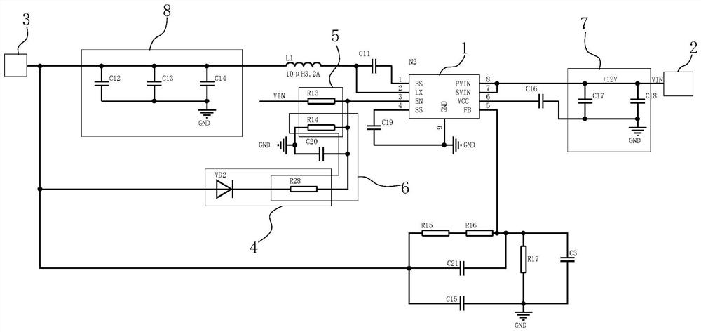
[0025] like figure 1 A preferred embodiment of the improved buck circuit of the present application is shown. The buck circuit includes a step-down chip 1 , the input end of the step-down chip 1 is connected to a power module 2 and the output end is connected to a load module 3 .

[0026] As described above, when the buck circuit is in use, it is easy to cause the input voltage to be unstable due to a disturbance signal or a change in the load, which in turn causes the output voltage to oscillate, affecting the normal operation of the c...


PUM


Abstract

The invention relates to an improved buck circuit which comprises a buck chip, the input end of the buck chip is connected with a power module, the output end of the buck chip is connected with a load module, and the buck circuit further comprises a hysteresis loopback module which loads the voltage of the output end of the buck chip to an enabling end of the buck chip. The enabling end of the buck chip is also connected with the power supply module, so that the voltage obtained by the enabling end is jointly determined by the power supply module and the output end voltage by utilizing the dynamic change characteristic between the enabling end of the buck chip and the input end voltage to ensure that when the circuit disturbs the voltage reduction of the power supply module, the voltage obtained by the enabling end is still greater than the enabling voltage so as to maintain the normal and stable output of the buck chip. The circuit is low in cost and good in anti-oscillation effect.

Description

technical field [0001] The invention relates to the field of electronic technology, in particular to an improved buck circuit. Background technique [0002] The buck circuit is widely used in lighting, electric meter systems and other fields. Now the common buck circuit divides the input voltage VIN to enable the buck chip. There is a threshold value of the enable pin EN of the buck chip. When the external input voltage When the divided voltage is greater than the threshold, the buck chip is enabled, and the circuit generates the output voltage VOUT. When the divided voltage of the external input voltage is less than the threshold of the chip, the chip is turned off, and the circuit does not generate the output voltage VOUT. [0003] This creates a problem. When the external input voltage is a supercapacitor or the input voltage is just near the enable voltage of the buck chip, if an interference signal is suddenly generated or the dynamic load changes, the input voltage wil...

Claims


Application Information

Patent Timeline
Patent Type & Authority Applications(China)
IPC IPC(8): H02M3/156
CPCH02M3/156
Inventor 胡志志山峰
Owner NINGBO SANXING MEDICAL & ELECTRIC CO LTD
Learn More