
Semiconductor integrated circuit device having polycrystalline silicon resistor circuit

a technology of resistor circuit and integrated circuit, which is applied in the direction of semiconductor devices, solid-state devices, basic electric elements, etc., can solve the problems of reducing the area of the resistor circuit, and achieve the effects of low resistance variation, high output voltage precision, and small area to implemen

Inactive Publication Date: 2009-02-03
ABLIC INC
View PDF2 Cites 3 Cited by
  • Summary
  • Abstract
  • Description
  • Claims
  • Application Information

AI Technical Summary

Benefits of technology

The present invention provides a resistor circuit that uses polycrystalline silicon resistors with low variation in resistance, high stability, and small area. The circuit includes a semiconductor substrate, insulating films, resistors, contact holes, metal wirings, and a second metal wiring covering the low concentration impurity region of each resistor. The length of the low concentration impurity region is longer at one end and shorter at the other end of the resistors connected in series. The circuit has high output voltage precision and small area to implement.

Problems solved by technology

However, a method for stabilization of the polycrystalline silicon resistance of the above-described resistor circuit has the following problem.
The problem is that: the metal wiring should be arranged to sufficiently cover the resistor in consideration for an alignment shift between the metal wiring and the polycrystalline silicon resistor and for preventing effect against the above-mentioned hydrogen diffusion when the metal electrode is disposed over the polycrystalline silicon resistor.
This hinders the reduction in area of the resistor circuit.

Method used


Image

  • Semiconductor integrated circuit device having polycrystalline silicon resistor circuit
  • Semiconductor integrated circuit device having polycrystalline silicon resistor circuit
  • Semiconductor integrated circuit device having polycrystalline silicon resistor circuit

Examples


Embodiment Construction

[0024]Hereinafter, description will be made of an embodiment of the present invention with reference to the drawings.

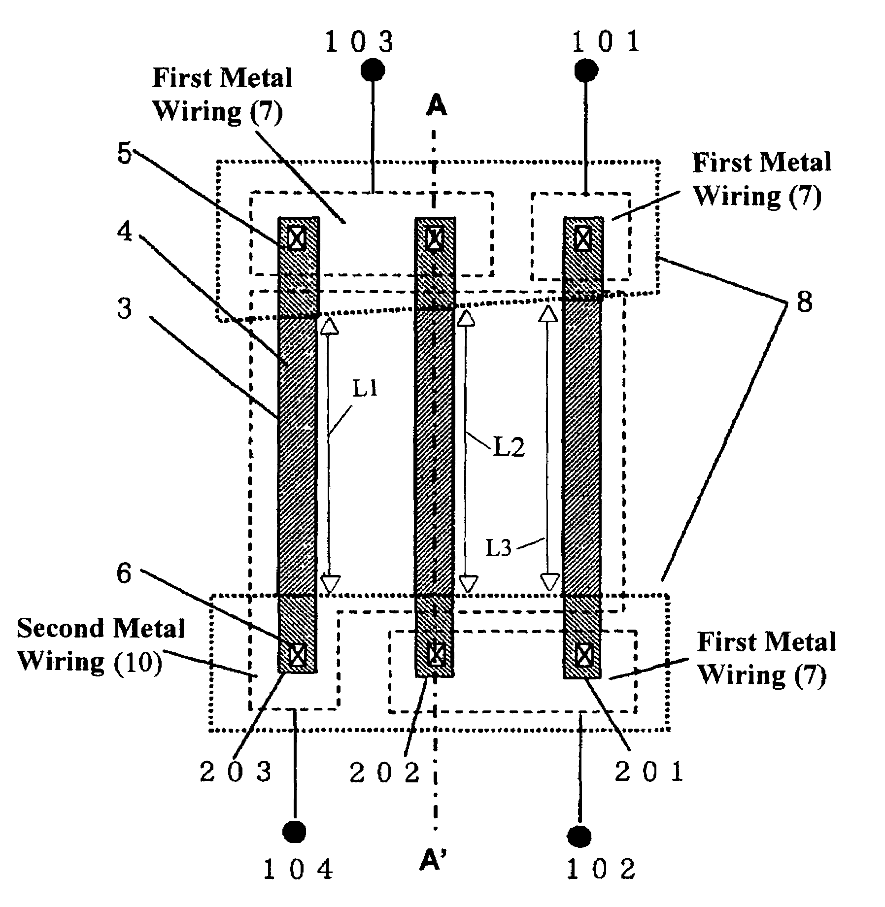
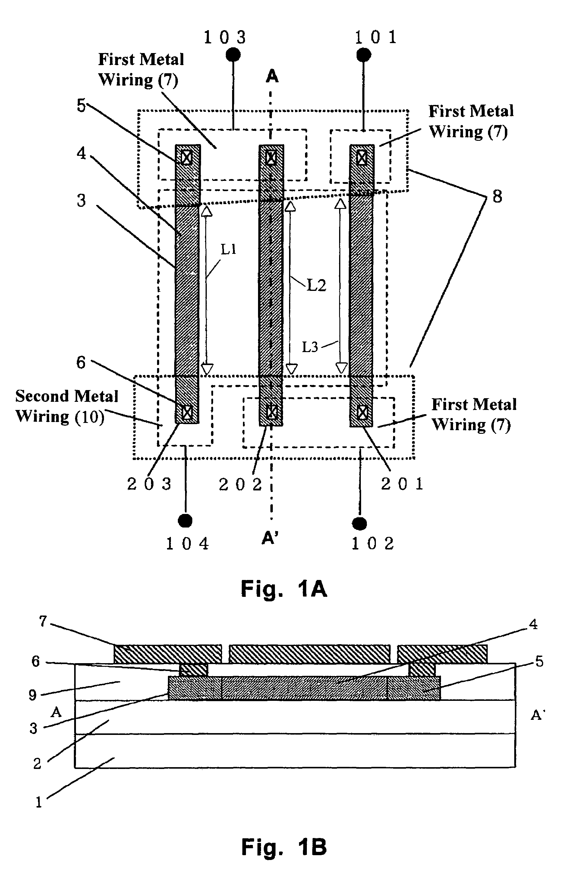
[0025]FIGS. 1A and 1B show an embodiment of the present invention for realizing a resistor circuit shown in FIG. 3. Resistors 1 (201) to 3 (203) are each formed of the polycrystalline silicon film 3 which is formed on the insulating film 2 on the semiconductor substrate 1 and which is composed of the low concentration impurity region 4 and a pattern 8 of the high concentration impurity regions 5 as in the prior art. The potential of the terminal A (101) and the terminal D (104) is taken out respectively through the metal wirings (first metal wirings 7 and second metal wirings 10) via the contact holes 6 formed in the second insulating film 9 and provided on the high concentration impurity regions 5.

[0026]However, in the prior art, as regards the metal wiring covering the resistor, there has been adopted the structure in which the metal wiring of one of the terminals c...


PUM


Abstract

A semiconductor device has a first insulating film formed on a semiconductor substrate and resistors disposed on the first insulating film. Each of the resistors is formed of a polycrystalline silicon film having a low concentration impurity region and high concentration impurity regions disposed on opposite sides of the low concentration impurity region. The low concentration impurity regions of the plurality of resistors have different lengths from one another. A second insulating film is disposed on the resistors. Contact holes are formed on the second insulating film and are disposed on the high concentration impurity regions. First metal wirings are connected to the respective contact holes and connect the resistors in series. A second metal wiring is connected to one of the resistors located at one end of the resistors connected in series. The second metal wiring covers the low concentration impurity region of all of the resistors.

Description

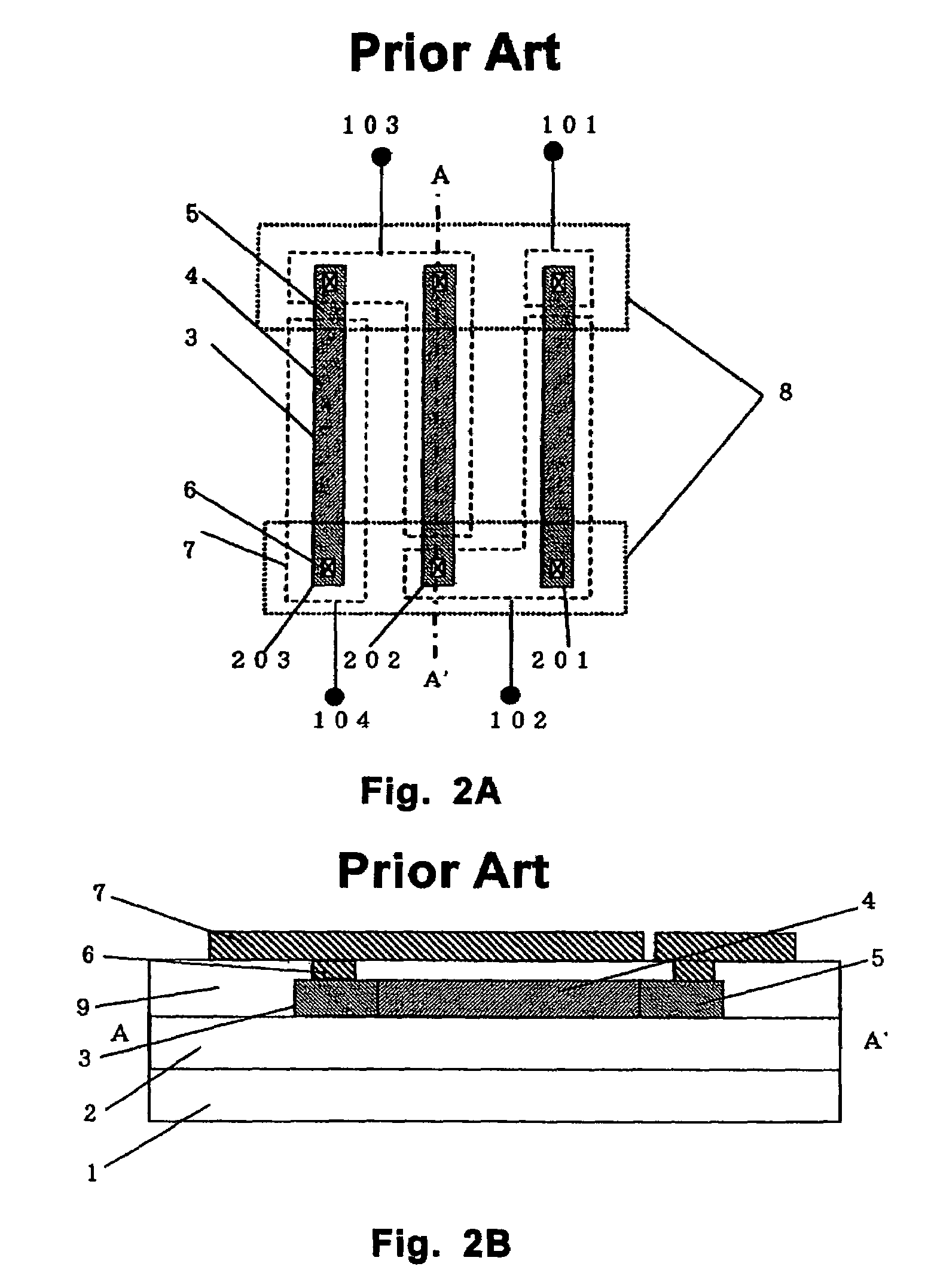
BACKGROUND OF THE INVENTION[0001]1. Field of the Invention[0002]The present invention relates to a semiconductor integrated circuit including a resistor circuit made of polycrystalline silicon.[0003]In a semiconductor integrated circuit, the following two resistors have been mainly used: a diffusion resistor, which is made of single crystalline silicon to which an impurity of an opposite conductivity to that of a semiconductor substrate is diffused, and a polycrystalline silicon resistor, which is made of polycrystalline silicon to which an impurity is diffused. Between the two, a polycrystalline silicon resistor has been widely used for a semiconductor integrated circuit because of its advantages, for example, that leak current is small since an insulating film surrounds the resistor, and that high resistance can be obtained owing to defects that exist at grain boundaries.[0004]2. Description of the Related Art[0005]FIGS. 2A and 2B show a conventional polycrystalline silicon resist...

Claims


Application Information

Patent Timeline
Patent Type & Authority Patents(United States)
IPC IPC(8): H01L29/76H01L29/94H01L31/062H01L31/113H01L31/119H01L21/822H01L27/04
CPCH01L27/0802H01L28/20Y10S257/904
Inventor HARADA, HIROFUMI
Owner ABLIC INC
Learn More