Supercharge Your Innovation With Domain-Expert AI Agents!

Low-voltage micro-switch actuation technique

a micro-switch and low-voltage technology, applied in the direction of electromagnetic relays, electrostrictive/piezoelectric relays, electrical apparatus, etc., can solve the problems of not being significantly commercialized, the pull-in voltage can be different from what the quasi-static analysis shows, and the device has not yet become significantly commercialized

Inactive Publication Date: 2009-02-03
MASSACHUSETTS INST OF TECH
View PDF22 Cites 9 Cited by
  • Summary
  • Abstract
  • Description
  • Claims
  • Application Information

AI Technical Summary

Benefits of technology

The invention is a switch structure that uses electricity to move a switch. The switch has two electrodes, one of which is fixed and one of which is movable. The voltage between the two electrodes is adjusted to inject energy into the switch until it is ready to be activated. The method for making this switch structure is also provided. The technical effect of this invention is to provide a more reliable and efficient way to activate switches using electricity.

Problems solved by technology

However, it has been shown that under dynamic conditions, the pull-in voltage can be different from what the quasi-static analysis predicts.
However, these devices have not yet become significantly commercialized.
Voltage up-converters are therefore necessary for these devices to operate in commercial applications which add cost, complexity, and power consumption.
While some electrostatic MEMS switches have been designed for low voltage operation by decreasing the structure stiffness, this has so far only been with a significant sacrifice in reliability and performance.
There are other actuation techniques, such as thermal or magnetic, that operate with lower voltages, however these are significantly slower than electrostatic switches and also consume much more power.

Method used


Image

  • Low-voltage micro-switch actuation technique
  • Low-voltage micro-switch actuation technique
  • Low-voltage micro-switch actuation technique

Examples


Embodiment Construction

[0013]The invention involves a technique that will allow the operation of MEMS switches with a significantly lower voltage without decreasing the stiffness. The actuation time will become slower but with the reduction in voltage that is potentially possible, some of this speed can be recovered by making the structure stiffer. This will have the side benefit of making the switch more reliable by reducing the chance of failure by stiction.

[0014]The technique described herein uses a modulated actuation voltage rather than the standard DC actuation voltage. This increases the complexity of the drive circuitry but allows the elimination of the off-chip voltage upconverters that would otherwise be necessary.

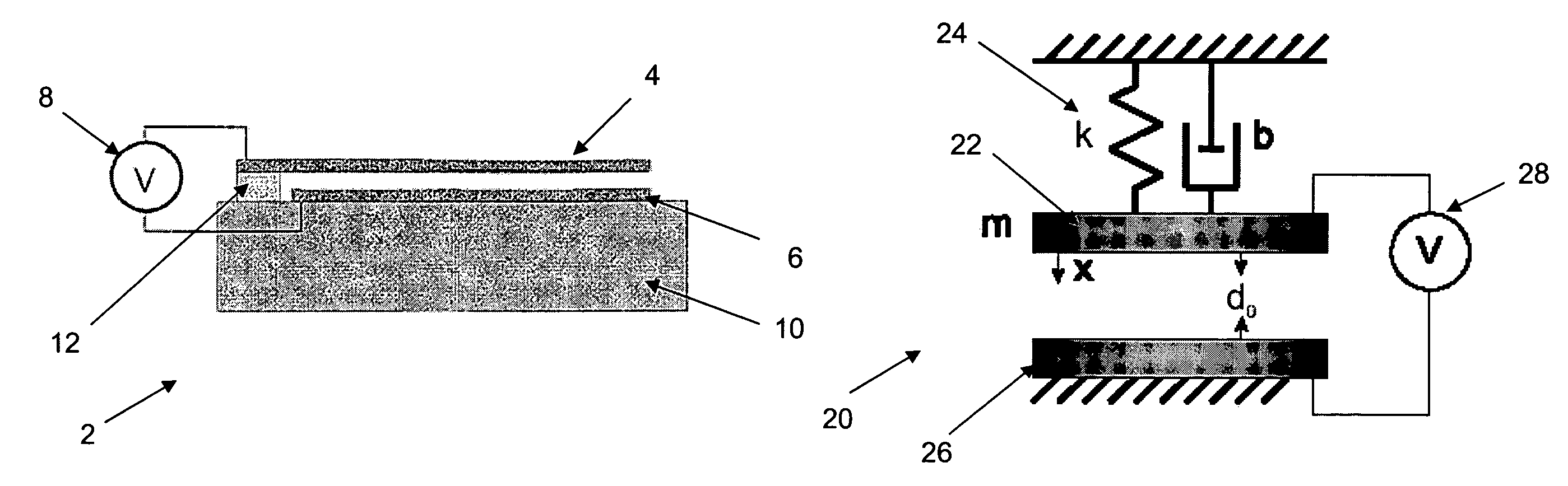
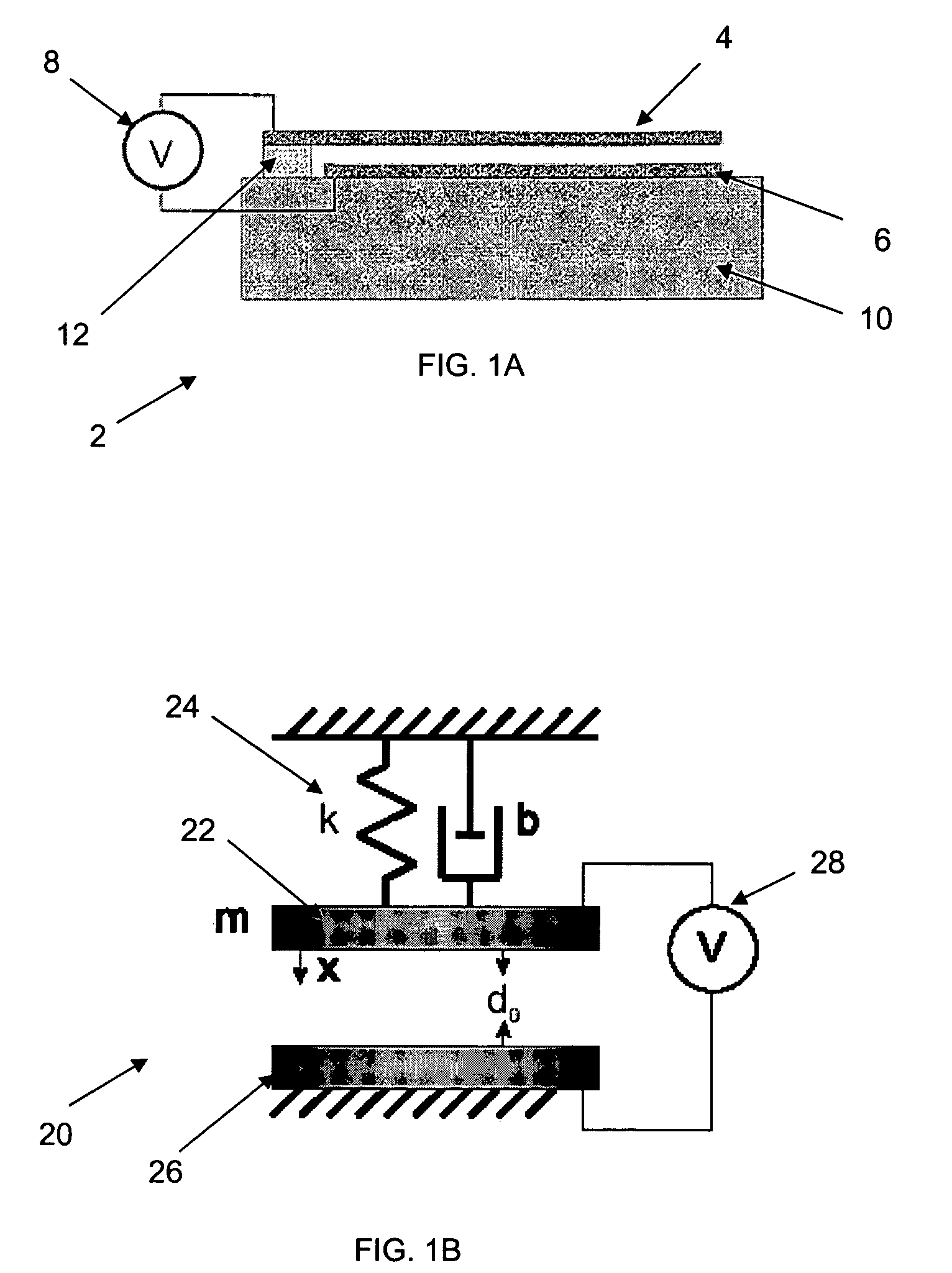
[0015]Consider the geometry shown in FIG. 1A, which illustrates a cantilever beam implementation of a parallel electrode actuator 2. The parallel electrode actuator 2 includes a free electrode 4, a fixed electrode 6, a voltage source 8 that is applied between the fixed electrode 6 and ...


PUM


Abstract

An electro-mechanical switch structure includes at least one fixed electrode and a free electrode which is movable in the structure with a voltage potential applied between each fixed electrode and the free, movable electrode. The voltage potentials applied between each fixed electrode and the movable electrode are modulated to actuate the electro-mechanical switch structure.

Description

PRIORITY INFORMATION[0001]This application claims priority to U.S. Provisional Patent Application No. 60 / 533,127, filed Dec. 30, 2003 which is incorporated herein by reference in its entirety.BACKGROUND OF THE INVENTION[0002]The invention relates to the field of micro-electro-mechanical systems (MEMS), and in particular a new actuation technique for MEMS switching that injects the energy required to actuate a switch over a number of mechanical oscillation cycles rather than just one.[0003]In MEMS parallel plate and torsional actuators, the pull-in phenomenon has been effectively utilized as a switching mechanism for a number of applications. Pull-in is the term that describes the snapping together of a parallel plate actuator due to a bifurcation point that arises from the nonlinearities of the system. Typically the analysis of the pull-in phenomena is performed using quasi-static assumptions. However, it has been shown that under dynamic conditions, the pull-in voltage can be diffe...

Claims


Application Information

Patent Timeline
Patent Type & Authority Patents(United States)
IPC IPC(8): H01H51/22H01H47/00H01H59/00
CPCH01H47/00H01H59/0009H01H2059/0054
Inventor NIELSON, GREGORY N.BARBASTATHIS, GEORGE
Owner MASSACHUSETTS INST OF TECH
Features
  • R&D
  • Intellectual Property
  • Life Sciences
  • Materials
  • Tech Scout
  • Unparalleled Data Quality
  • Higher Quality Content
  • 60% Fewer Hallucinations
Learn More