
Safety condition setting support device, program product and device control method for obtaining safety condition for safety network

a technology of safety network and safety condition, which is applied in the direction of electric controllers, program control, electric programme control, etc., can solve the problems of cumbersome network routine determination, inability to identify, and inability to meet the requirements of safety network, and achieve the effect of reducing the number of network routines

Active Publication Date: 2009-02-03
ORMON CORP
View PDF16 Cites 6 Cited by
  • Summary
  • Abstract
  • Description
  • Claims
  • Application Information

AI Technical Summary

Benefits of technology

[0014]It is therefore an object of this invention in view of the above to provide a safety condition setting support device and a computer readable medium program product as well as a method of controlling a device for obtaining safety conditions for a safety network such that various parameters (such as safety distances and intervals for signal transmission from various apparatus) for constructing a safety network can be set even in situations where the specifications, etc of each apparatus are not fully understood, that no excessive communication capability or unnecessary safety distance will be set, that data for constructing a realizable safety network can be provided, and that a safety network system can be constructed while the whole system structure can be grasped visually and in a sensory manner by carrying out processes by following a displayed screen.
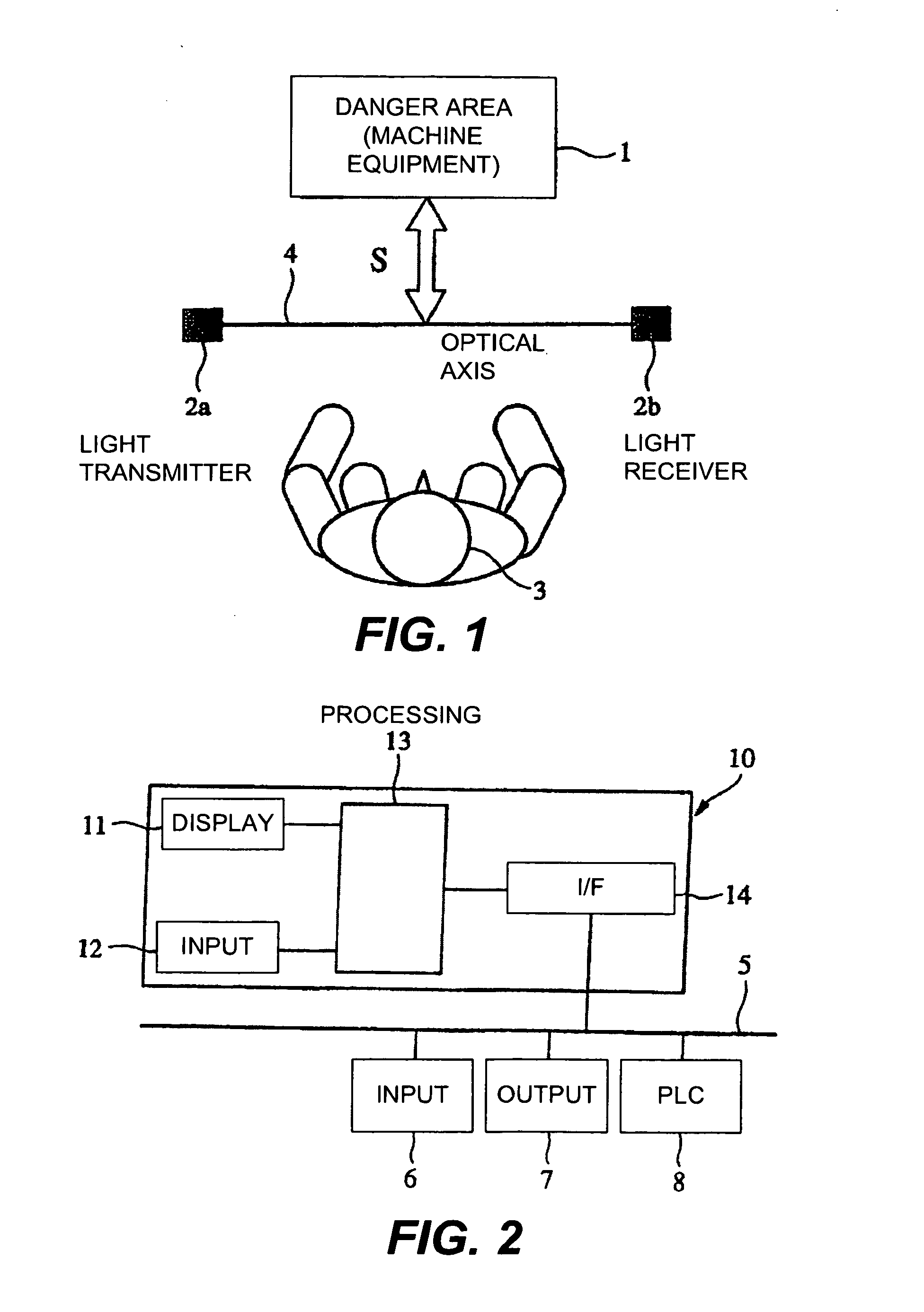
[0018]In order to dependably carry out this safety operation, there are two methods to be considered, one being to shorten as much as possible the total time from when the input device detects an abnormal condition until the output device issues a stop command to the controlled apparatus and stops it and the other being to detect the abnormality (such as the invasive entry of a person) at a position as far as possible from the danger area. In actual applications, a decision is suitably made according to the mutual relationship between these two, that is, if the total time is determined, the minimum distance (safety distance) to be maintained between the detection position by the input device and the danger area can be determined from the walking speed of the person, etc. In reverse, if the distance between the detection position by the input device and the danger area is fixed, it is possible to obtain the aforementioned total time for making it equal to a safety distance.
[0019]Since the internal processing times of the safety devices are stored in the apparatus data memory according to this invention, a total processing time required for transmitting a detection signal indicating an abnormal condition can be obtained easily by adding the processing times by the connected safety devices and the transmission interval. Thus, if the transmission interval is given, since the total processing time can be obtained therefrom as explained above, it is possible to calculate a safety distance (or its recommended value). If the transmission interval is unknown but the safety distance has been inputted, on the other hand, it is possible to obtain a transmission interval (or its recommended value). If both the transmission interval and the safety distance have been inputted, it is possible to determine whether the safety condition is satisfied by the inputted conditions.
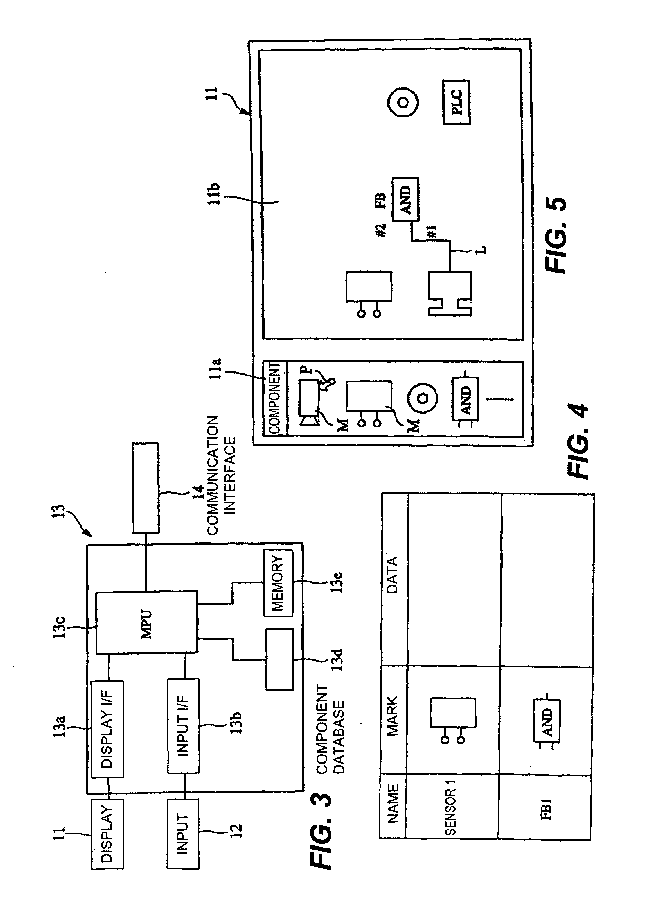
[0024]In summary, the user can obtain the safety conditions that are necessary for constructing a safety network system merely by carrying out processes that are simple and easy to visually ascertain such as positioning and connecting devices to be used while watching the display screen (or just by selecting them).

Problems solved by technology

Prior art systems of this type had problems of the following kind.
It is troublesome, however, to identify the devices that form the network system related to the machine equipment and to obtain times related to them.
Thus, it is cumbersome to determine the network routine for which a safety distance is now being sought and to consider the delay in the communication time based on it.
In view of the above, it is possible to consider all delays related to the network to be uniform and for the user to set up all machine apparatus by calculating safety distances for them all by taking into consideration their maximum delay but if the delay times and the processing times are uniform, there is no flexibility in the application and applicable applications become limited.
If the fastest response time (internal processing time) is required of all apparatus, furthermore, this will require an excessive communication capability of the safety network to be used and this will adversely affect the cost.

Method used


Image

  • Safety condition setting support device, program product and device control method for obtaining safety condition for safety network
  • Safety condition setting support device, program product and device control method for obtaining safety condition for safety network
  • Safety condition setting support device, program product and device control method for obtaining safety condition for safety network

Examples


Embodiment Construction

[0051]The invention is described with reference to the drawings.

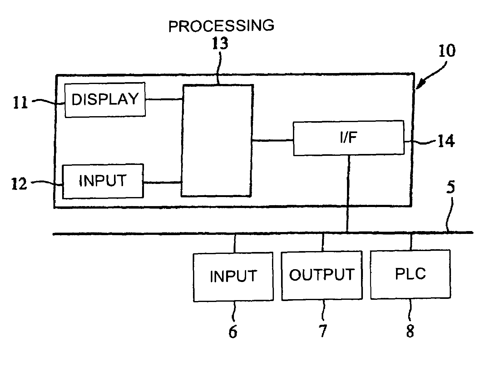
[0052]FIG. 2 shows an embodiment of the invention. As shown, a safety network system is structured by connecting various devices corresponding to a safety network such as an input device 6, an output device 7 and a PLC 8 to a network 5 such that data can be exchanged between specified devices.

[0053]In order to form such a safety network system in an actually operable condition, it is necessary to download programs of various kinds. In order to carry out data communications between the PLC 8 and a slave (the input and output devices 6 and 7), furthermore, it is necessary to assign the I / O of the slave to the memory of the PLC 8. This is the same also for communications between the slaves. A tool 10 is adapted to be used for creating such programs and also to be connected to the network 5 for downloading programs to a specified device or to carry out memory assignments.

[0054]Next, the network system which is finally struc...


PUM


Abstract

A safety condition setting support device is used for a safety network to which an input device and an output device are connected and the output device serves to stop a controlled apparatus based on a detection signal outputted from the input device when the input device has detected a danger condition. The support device serves to set safety conditions for stopping the controlled apparatus within a specified time period and includes an apparatus data memory for storing data related to internal processing times of safety devices connected to the safety network including the input and output devices, data obtaining device obtaining connection data showing connection relationship among the safety devices and transmission intervals among the safety devices or a safety distance between the input device and the controlled apparatus, and a calculating device for obtaining the safety conditions based on these obtained data.

Description

[0001]This application is a continuation of International Application No. PCT / JP2003 / 02702, filed Mar. 7, 2003, which claims priority based on Japanese Patent Application 2002-62593 filed Mar. 7, 2002.BACKGROUND OF THE INVENTION[0002]This invention relates to a safety condition setting support device and a computer readable medium program product, as well as a method of controlling a device for obtaining safety conditions for a safety network.[0003]As is well known, a network system connecting a programmable controller (PLC) and a slave through a network such as a device network is structured for a factory automation (FA) system. The slave is provided with a plurality of I / O units and sensors, relays and apparatus of various other kinds and connected to these I / O units such that sensing data detected by input devices (such as switches and sensors) connected to the slave, for example, are taken in by the PLC through the network. The PLC serves to analyze the obtained sensing data and...

Claims


Application Information

Patent Timeline
Patent Type & Authority Patents(United States)
IPC IPC(8): G05B11/01G05B19/05
CPCG05B19/058
Inventor MUNETA, YASUO
Owner ORMON CORP
Learn More