Configuration of Security Devices Using Spatially-Encoded Optical Machine-Readable Indicia

a technology of optical machine-readable indicia and security device, which is applied in the direction of program control, instruments, testing/monitoring control systems, etc., can solve the problem that the installer will incorrectly enter at least some configuration information, and achieve the effect of configuring a security network

Active Publication Date: 2014-08-07
JOHNSON CONTROLS TYCO IP HLDG LLP
View PDF3 Cites 14 Cited by
  • Summary
  • Abstract
  • Description
  • Claims
  • Application Information

AI Technical Summary

Benefits of technology

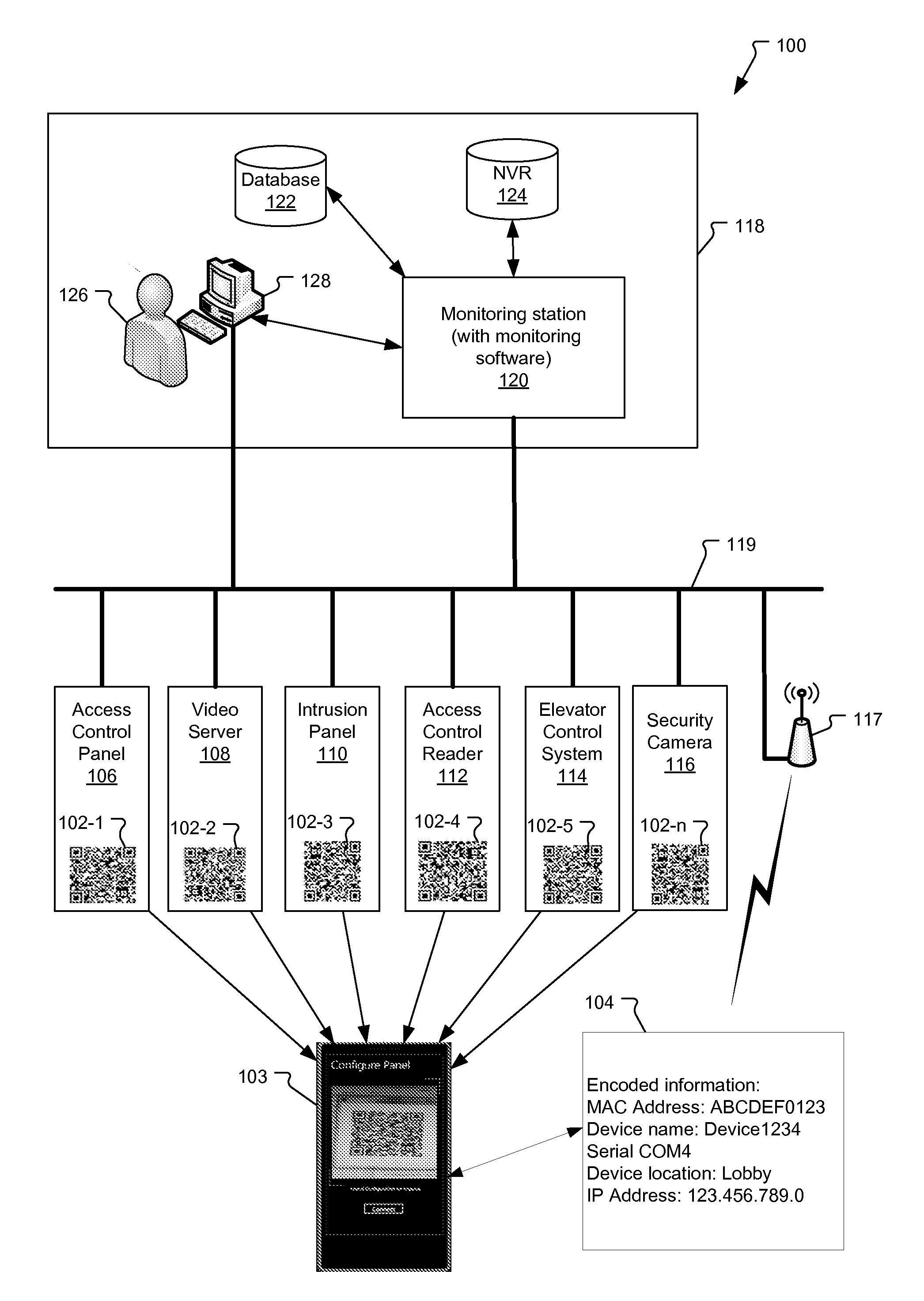
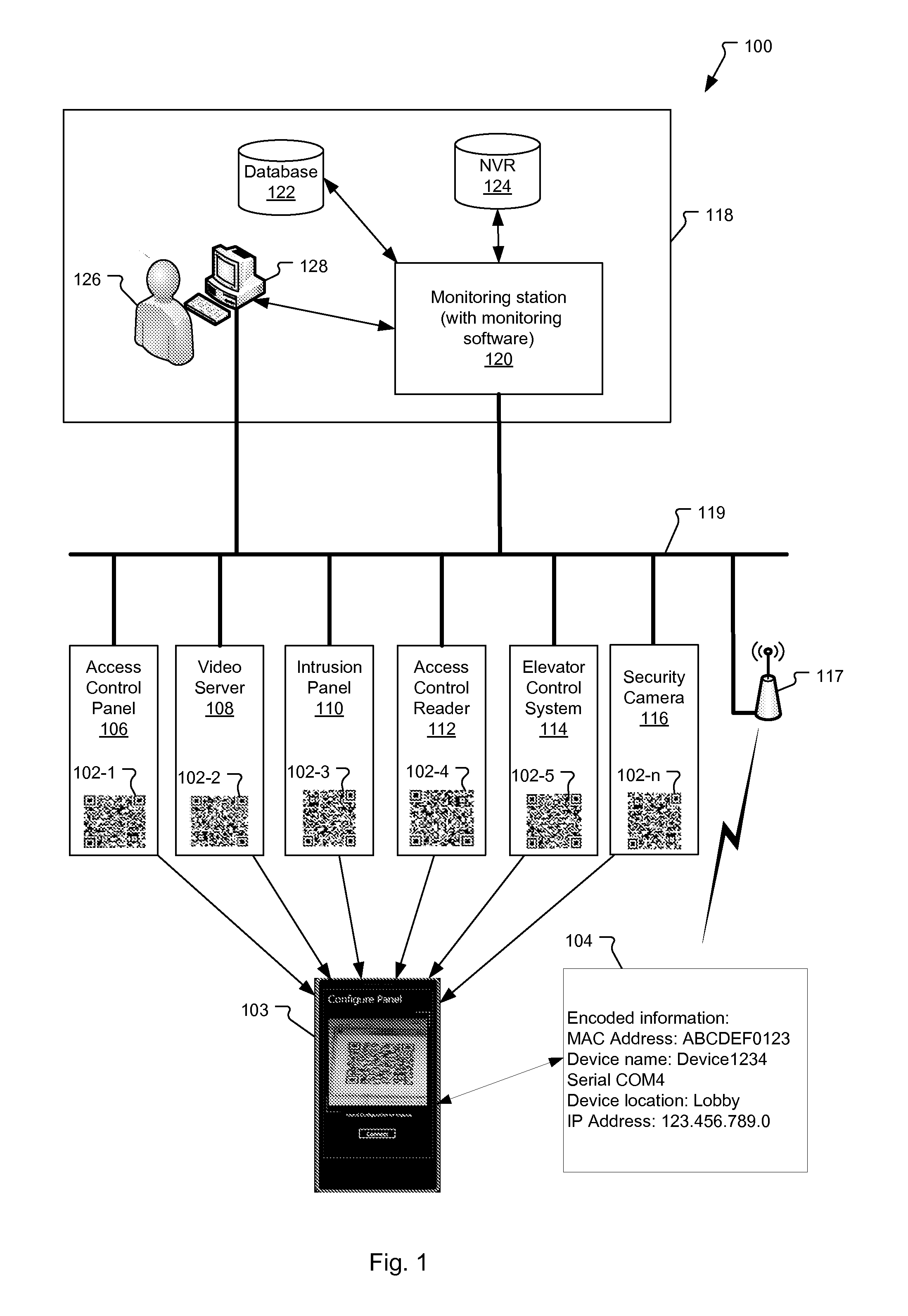
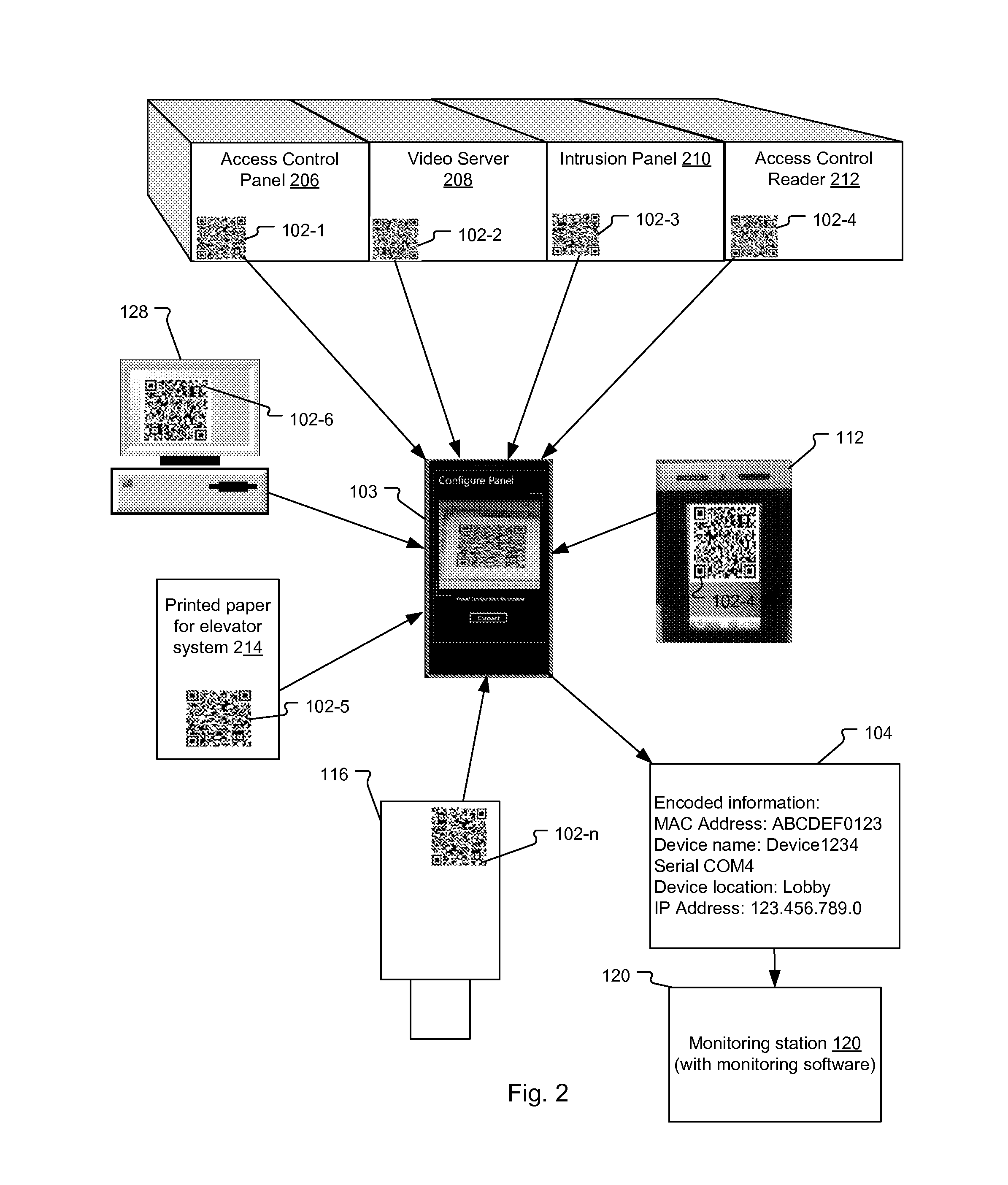
[0006]The present solution is directed to using a mobile computing device, for example, to extract configuration information of the security devices from spatially-encoded optical machine-readable indicia such as two-dimensional bar codes (or matrix bar codes), one-dimensional bar codes, and / or other machine readable indicia.
[0007]In one example, a mobile computing device reads an indicium, decodes the indicium, and extracts the configuration information. The configuration information from the indicium is then entered into a configuration client executing on the mobile computing device. The configuration information is then transmitted from the mobile computing device to the security system, such as a monitoring station, which uses the configuration information to communicate and / or control the security devices on the security network of the security system.
[0008]In general, according to one aspect, the invention features a method for configuring a security network. The method includes reading spatially-encoded optical machine-readable indicia with a mobile computing device, the spatially-encoded optical machine-readable indicia being associated with and encoding configuration information for the security devices. The method further includes decoding the configuration information from the spatially-encoded optical machine-readable indicia and using the configuration information to configure communication with the security devices on a security network of the security system.
[0009]In general, according to another aspect, the invention features a security system with security network configuration capability. The system includes security devices for installation in a security network. Spatially-encoded optical machine-readable indicia are associated with the security devices. They encode configuration information of the security devices. A mobile computing device is used to read the indicia and decode the configuration information. A monitoring station is provided for monitoring the security devices in the security network; the monitoring station uses the configuration information from the mobile computing device to configure communication with the security devices over the security network.
[0010]In general, according to another aspect, the invention features a security device package. The security device package includes a security device for installation in a security network and a spatially-encoded optical machine-readable indicium that is associated with the security device that encodes security network configuration information.
[0011]The above and other features of the invention including various novel details of construction and combinations of parts, and other advantages, will now be more particularly described with reference to the accompanying drawings and pointed out in the claims. It will be understood that the particular method and device embodying the invention are shown by way of illustration and not as a limitation of the invention. The principles and features of this invention may be employed in various and numerous embodiments without departing from the scope of the invention.

Problems solved by technology

Because the installation and configuration for the security devices is time consuming and susceptible to human errors, it is probable that the installer will incorrectly enter at least some of the configuration information.

Method used


Image

  • Configuration of Security Devices Using Spatially-Encoded Optical Machine-Readable Indicia
  • Configuration of Security Devices Using Spatially-Encoded Optical Machine-Readable Indicia
  • Configuration of Security Devices Using Spatially-Encoded Optical Machine-Readable Indicia

Examples


Embodiment Construction

[0018]The invention now will be described more fully hereinafter with reference to the accompanying drawings, in which illustrative embodiments of the invention are shown. This invention may, however, be embodied in many different forms and should not be construed as limited to the embodiments set forth herein; rather, these embodiments are provided so that this disclosure will be thorough and complete, and will fully convey the scope of the invention to those skilled in the art.

[0019]As used herein, the term “and / or” includes any and all combinations of one or more of the associated listed items. Further, the singular forms of the articles “a”, “an” and “the” are intended to include the plural forms as well, unless expressly stated otherwise. It will be further understood that the terms: includes, comprises, including and / or comprising, when used in this specification, specify the presence of stated features, integers, steps, operations, elements, and / or components, but do not prec...


PUM


Abstract

A method and system for configuring security devices on a security network. A mobile computing device reads spatially-encoded optical machine-readable indicia, decodes the indicia, and extracts encoded configuration information for the security devices. The configuration information from the indicia is then transmitted to a monitoring station, which uses the configuration information to configure communication with the security devices on the security network.

Description

BACKGROUND OF THE INVENTION[0001]Security systems are often deployed in schools, government buildings, and corporate offices, and even many residences. These security systems are comprised of security devices such as door controllers, security cameras, access control readers, video servers, access control panels, intrusion panels, and elevator control systems, to list a few examples.[0002]Generally, the security devices are used to monitor locations in and around buildings and enable authorized users to access restricted areas through locked doors, for example. Typically, the security devices are connected to a security network and are controlled by a control system (or monitoring station). In an example, an access control reader reads an employee keycard while a security camera simultaneously monitors and records the employee's movements. If the employee is authorized to access the restricted area, then the monitoring station instructs the door controller to unlock the door.[0003]T...

Claims


Application Information

Patent Timeline
Patent Type & Authority Applications(United States)
IPC IPC(8): H04L29/06
CPCH04L63/08G08B25/003G08B25/14H04L63/20H04W12/04H04L67/34H04L63/10H04W12/37H04W12/77H04L41/0803
Inventor MAHAPATRA, SARTHAKKALYANARAMAN, CHANDRASEKARAN
Owner JOHNSON CONTROLS TYCO IP HLDG LLP
Why Eureka
Try Eureka