
Selectable beam lens for underwater light

a technology of underwater light and beam lens, which is applied in the direction of lens, coupling device connection, lighting support device, etc., can solve the problems of wrong type of lens being delivered or even installed at a use site, high manufacturing cost, added expense,

Active Publication Date: 2009-02-10
PENTAIR WATER POOL & SPA INC
View PDF24 Cites 26 Cited by
  • Summary
  • Abstract
  • Description
  • Claims
  • Application Information

AI Technical Summary

Benefits of technology

Enables efficient and cost-effective illumination in wet environments by allowing a single lens to produce multiple beam patterns through adjustable positioning, reducing inventory and installation complexities while ensuring accurate beam orientation.

Problems solved by technology

As can be appreciated, such manufacture, supply, etc., is costly and time consuming.
Moreover, there may also the added expense, etc. created by a wrong type of lens being delivered or even installed at a use site.

Method used


Image

  • Selectable beam lens for underwater light
  • Selectable beam lens for underwater light
  • Selectable beam lens for underwater light

Examples


Embodiment Construction

[0019]Certain terminology is used herein for convenience only and is not to be taken as a limitation on the present invention. Further, in the drawings, the same reference numerals are employed for designating the same elements throughout the figures, and in order to clearly and concisely illustrate the present invention, certain features may be shown in schematic form.

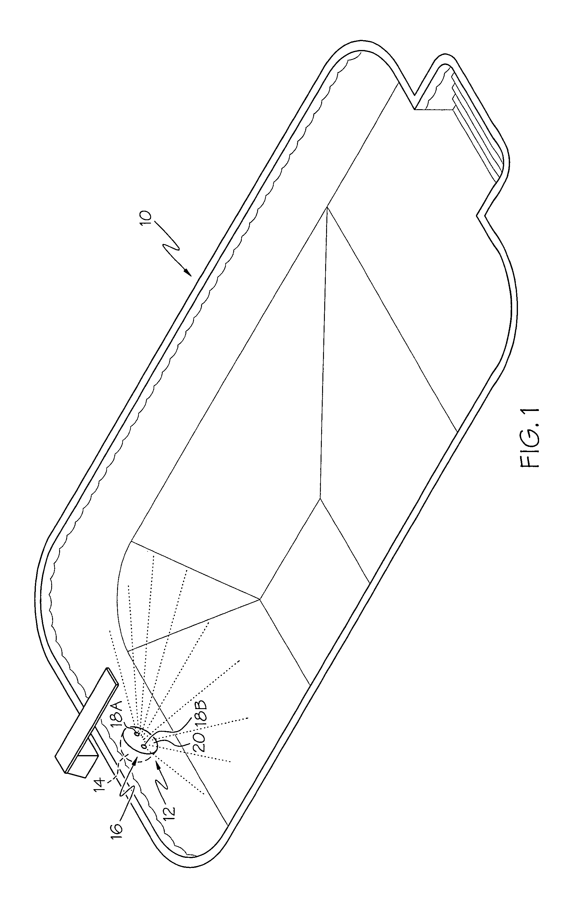
[0020]FIG. 1 shows an example wet environment 10, which happens to be an aquatic environment, in which a lighting device 12 in accordance with one aspect of the present invention can be used to provide illumination. It should be appreciated that the present invention can be used in various other wet environments. Some examples of such other wet environments include spas, baths, ponds, fountains, water spraying devices, and the like. Herein, the wet environment 10 is presented as a swimming pool 10. However, the swimming pool 10 is not a limitation on the present invention.

[0021]In the shown example, the lighting devic...


PUM


Abstract

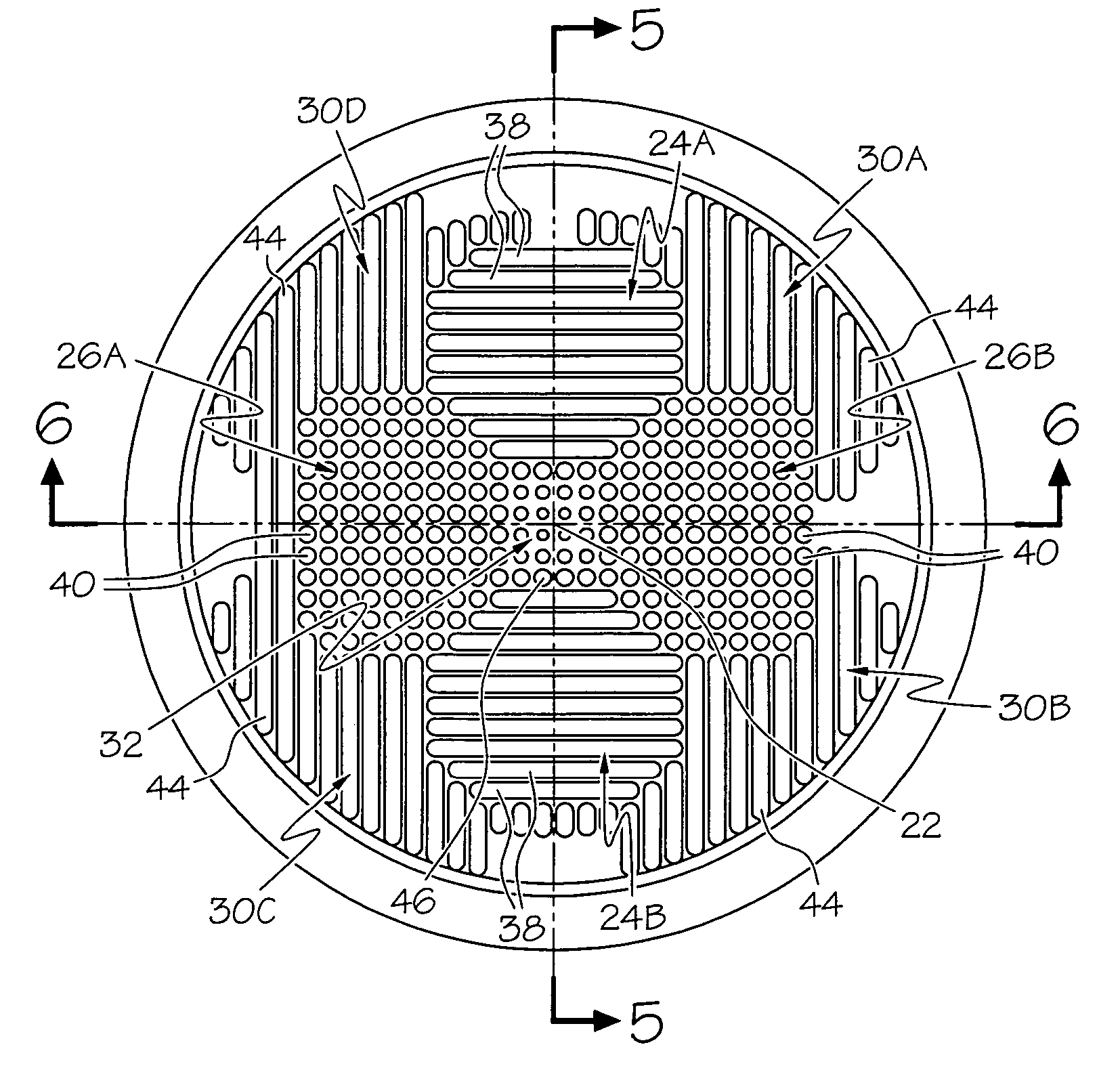
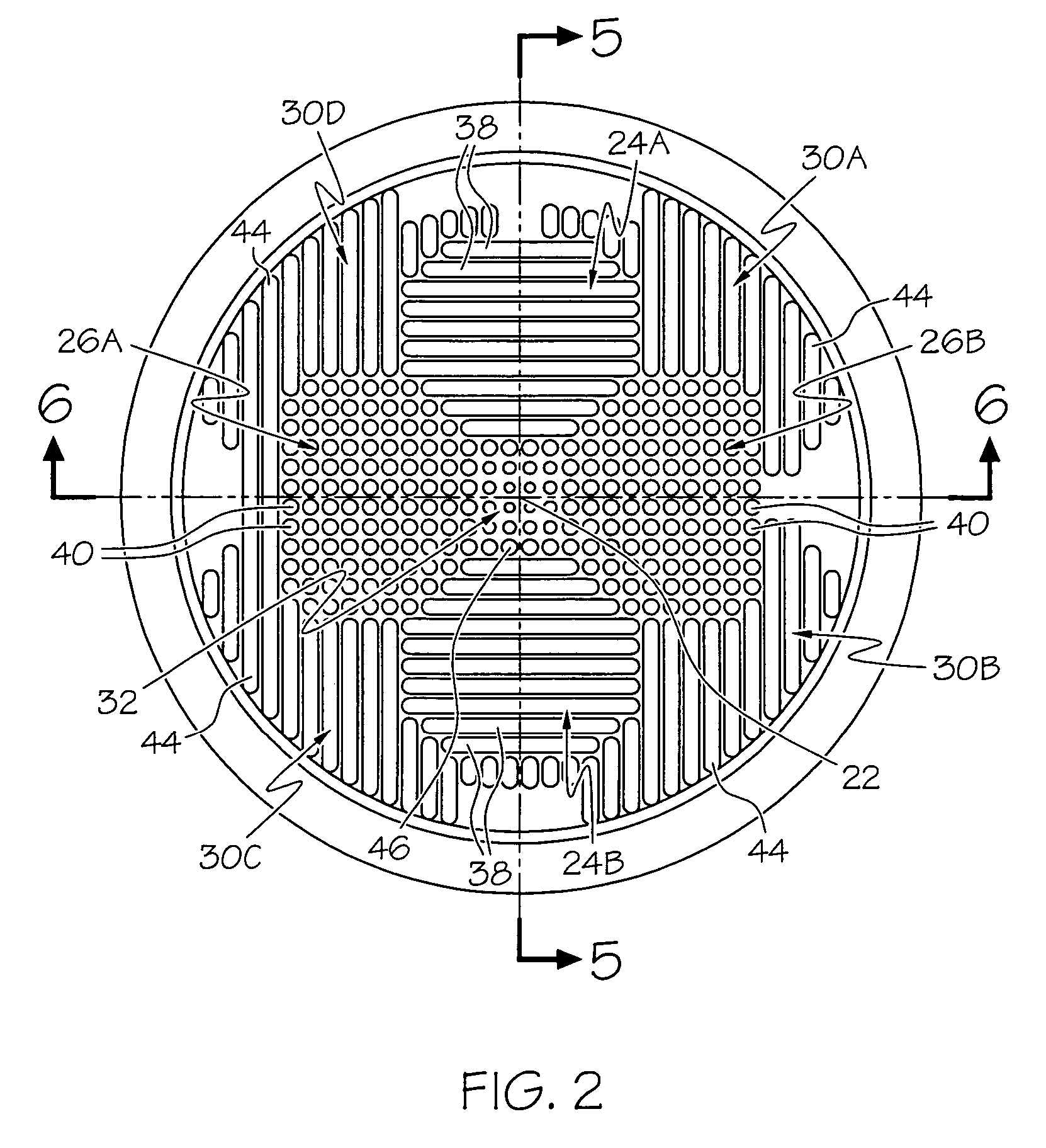
A lens for a wet environment lighting device that has a fixture with an interior that has an opening, and at least one light source located within the fixture interior. Light from the light source proceeds out through the opening. The lens is for location in front of the fixture and the light source located therein and the lens encloses the opening from the wet environment. The lens has a first light-directing area for directing light in a first beam pattern. The lens also has a second light-directing area, distinct from the first light-directing area, for directing light in a second beam pattern, distinct from the first beam pattern. The lens is positioned relative to fixture and light source therein to select from the distinct beam patterns based on the alignment of the light-directing areas relative to the light source resulting from a positioning of the lens.

Description

CROSS-REFERENCE TO RELATED APPLICATIONS[0001]This application claims the benefit of U.S. Provisional Application No. 60 / 623,607 filed on Oct. 29, 2004, which is entirely incorporated herein by reference.BACKGROUND OF THE INVENTION[0002]Lights that operate in a wet environment are known. One example of such a wet environment light is an underwater light that is within an aquatic environment. One example of an aquatic environment is a swimming pool.[0003]Underwater lights have different objectives depending on the shape and dimension of the aquatic environment that has to be illuminated and the relative locations of the lights therein. In one case, the objective could be to deliver light longitudinally (horizontally), while in another, the object could be to deliver a homogeneous illumination in all directions (horizontally and vertically). Presently, such different objectives are accomplished by manufacturing lenses designed specifically to achieve the desired beam patterns. Such an ...

Claims


Application Information

Patent Timeline
Patent Type & Authority Patents(United States)
IPC IPC(8): F21V33/00
CPCF21S8/00F21V5/02F21V5/04G02B3/02F21V5/002F21W2131/401F21Y2101/02F21Y2113/00F21Y2115/10
Inventor POTUCEK, KEVINDUNN, DENNIS
Owner PENTAIR WATER POOL & SPA INC
Learn More