Electric connection box

a technology of electric connection box and circuit board, which is applied in the direction of multiple connection sub-assemblies, cooling/ventilation/heating modification, printed circuits, etc., can solve the problems of limited space for electric connection box in the vehicle, damage to electronic components mounted on the circuit board, etc., to improve heat-releasing properties, increase air temperature, and reduce air density

Inactive Publication Date: 2009-02-10
AUTONETWORKS TECH LTD +2
View PDF11 Cites 7 Cited by
  • Summary
  • Abstract
  • Description
  • Claims
  • Application Information

AI Technical Summary

Benefits of technology

[0012]According to the present invention, the partition wall is provided for separating the heat generating component from the electronic component, and thereby heat from the heat generating component can be prevented from reaching the electronic component.
[0013]Further, the outside air can flow into the casing through the first inlet port, and the heat generating component disposed in the first air passage is exposed to the flowing air. Thereby the heat from the heat generating component is transferred to the air, resulting in increase in air temperature or decrease in air density inside the first air passage. The air inside the first air passage convects upward due to the chimney effect, and flows out through the first outlet port. Thereby the heat generated from the heat generating component can be effectively discharged to the outside of the casing.
[0014]Thus, the electric connection box of the present invention has an improved heat-releasing property. Negative pressure resulting from rising air in the first air passage facilitates the outside air flowing into the casing, and thereby further efficient cooling of the heat generating component can be achieved.

Problems solved by technology

However, limited space for the electric connection box can be provided in the vehicle, and therefore the relays should be mounted in the electric connection box in higher density.
However, in the case that relays are mounted on the bus-bar board as described above, there arises a problem that the electronic components mounted on the circuit board may be damaged due to heat generated by the relays.

Method used


Image

  • Electric connection box
  • Electric connection box
  • Electric connection box

Examples


first embodiment

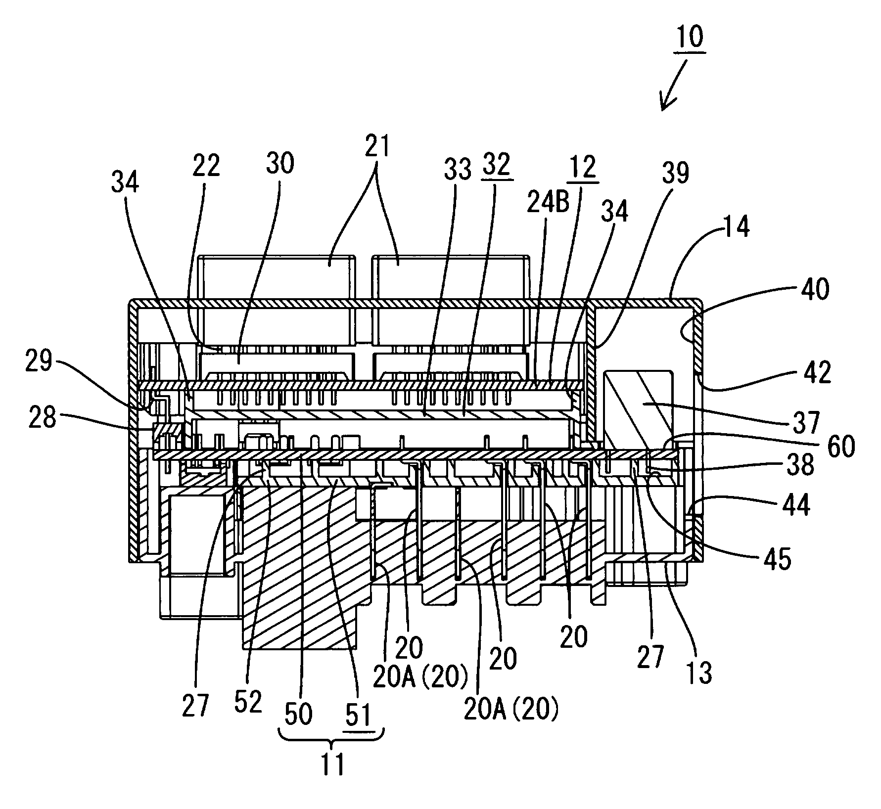
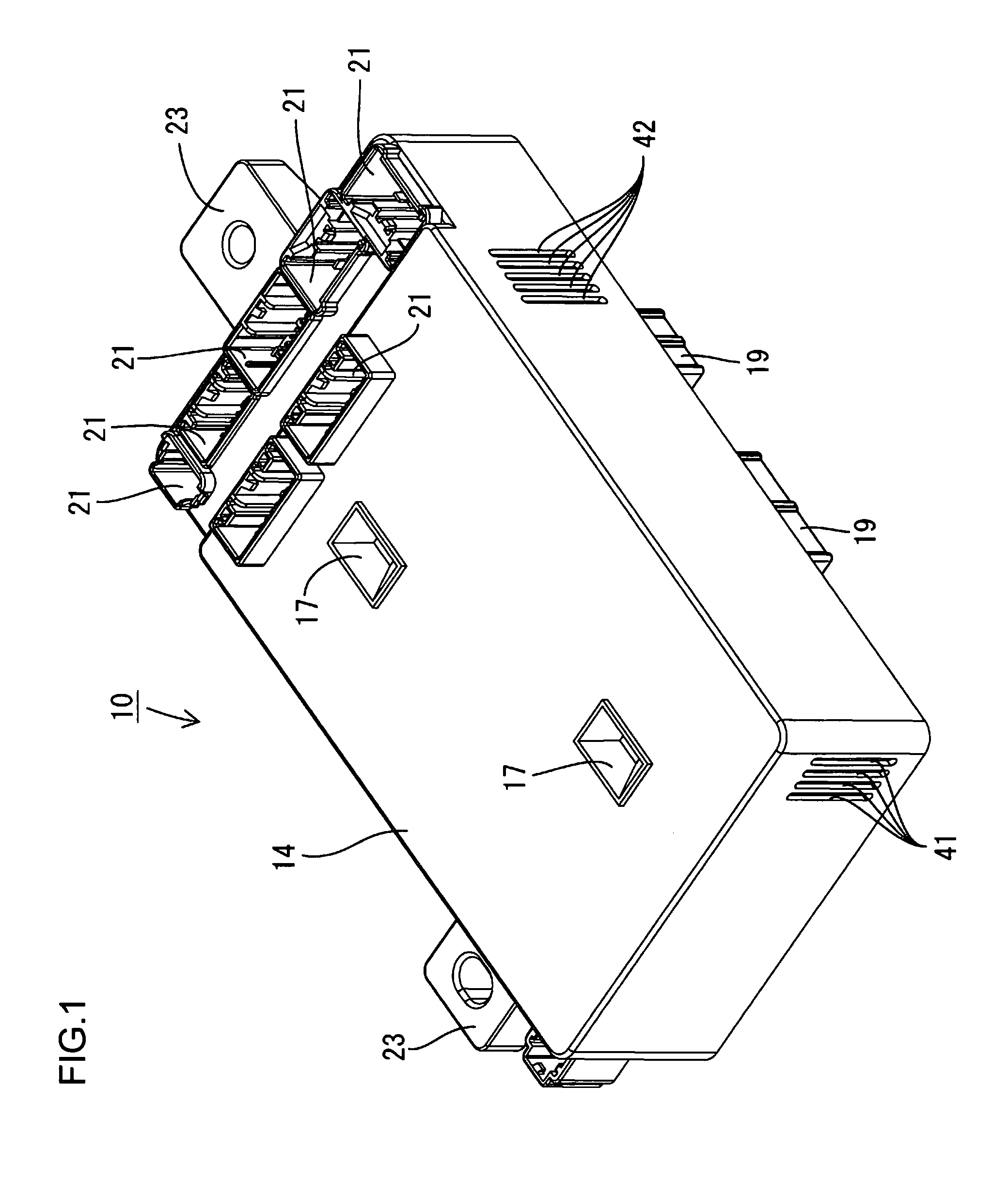
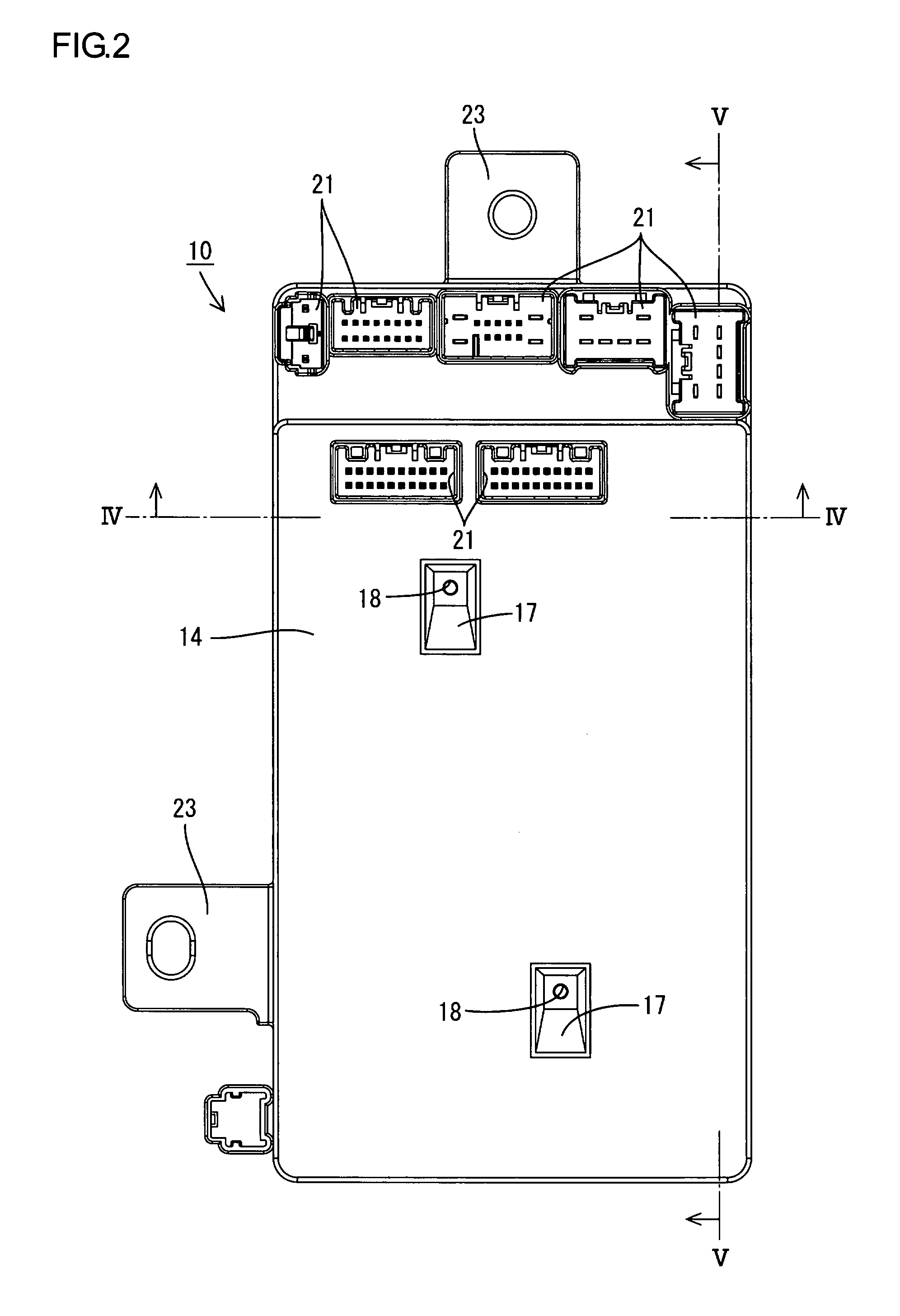
[0023]A first embodiment of the present invention will be explained with reference to FIGS. 1 through 5. An electric connection box of the present embodiment can be installed on a vehicle (not shown), and used for ON / OFF control of vehicle electronic components (not shown) such as a lamp or a power window. Specifically, the electric connection box is disposed between a battery (not shown) and the vehicle electronic components.

[0024]Referring to FIG. 1, the electric connection box has a rectangular flat casing 10 made of synthetic resin, and is mounted with its flat surfaces upright in the passenger compartment of the vehicle. That is, the lower left side of FIG. 1 is the bottom or lower side of the electric connection box, while the upper right side of FIG. 1 is the top or upper side.

[0025]Hereinafter, the front side of FIG. 1 is referred to as the first side of the electric connection box, while the back side of FIG. 1 is referred to as the second side. Further, the lower right sid...

second embodiment

[0085]Next, a second embodiment of the present invention will be explained with reference to FIG. 6.

[0086]In the present embodiment, an electric connection box does not include a bus-bar board 51 (or an insulating substrate 52), which is included in the first embodiment. That is, a power circuit board 11 is formed of one substrate (i.e., a thick film substrate 50) in the present embodiment. A plurality of bus bars 20 are mounted on the thick film substrate 50 so that the proximal end of each bus bar 20 penetrates the thick film substrate 50.

[0087]The other constructions are similar to the first embodiment. Therefore the similar constructions are designated by the same symbols as the first embodiment, and redundant explanations are omitted.

[0088]A second air passage 45 for allowing air to flow vertically is formed along the second-side (the lower-side in FIG. 6) surface of the power circuit board 11. Specifically, the second air passage 45 is formed between the power circuit board 11...


PUM


Abstract

An electric connection box includes an electronic circuit board having an electronic component, and a power circuit board having a power circuit, which are disposed upright in a casing. A vertically-extending component area for mounting a heat generating component is formed on the power circuit board, so as not to face the electronic circuit board. A partition wall for separating the component area from the electronic circuit board is provided in the casing, and thereby a first air passage for allowing air to flow vertically along the component area is formed in the casing. A first inlet port connected to the first air passage is formed on the casing, and a first outlet port connected to the first air passage and positioned above the first inlet port is formed on the casing.

Description

CROSS REFERENCE TO RELATED APPLICATION[0001]The present application is based on and incorporates herein by reference Japanese Patent Application No. 2006-328350 filed on Dec. 5, 2006.BACKGROUND OF THE INVENTION[0002]1. Field of the Invention[0003]The present invention relates to an electric connection box.[0004]2. Description of Related Art[0005]An electric connection box shown in JP-A-H9-214158 is conventionally provided. The electric connection box is installed on a vehicle, and used for ON / OFF control of vehicle electrical components. In the electric connection box, a bus-bar board and a circuit board are vertically disposed in a casing, and arranged parallel to each other. A plurality of bus bars constituting a power circuit are arranged on the bus-bar board, while electronic components are mounted on the circuit board.[0006]Further, relay attachment portions for connecting relays are provided on the wall of the casing. The number of relays to be connected to the electric connec...

Claims


Application Information

Patent Timeline
Patent Type & Authority Patents(United States)
IPC IPC(8): H01R12/00
CPCH05K7/026
Inventor HASHIKURA, MANABUSUMIDA, TATSUYA
Owner AUTONETWORKS TECH LTD
Why Eureka
Try Eureka