Memory card connector

a memory card and connector technology, applied in the field of connectors, can solve the problems of increasing the size of the electric appliance in itself, the inability of the antenna to be built in this memory card, etc., and achieve the effect of extending the communication distan

Inactive Publication Date: 2009-02-10
MATSUSHITA ELECTRIC WORKS LTD +1
View PDF6 Cites 9 Cited by
  • Summary
  • Abstract
  • Description
  • Claims
  • Application Information

AI Technical Summary

Benefits of technology

[0007]Therefore, a primary concern of the present invention is to provide a compact memory card connector, which has the capability of extending communication distance.
[0011]According to the connector of the present invention, the antenna block having the secondary antenna is slidable in the insertion direction of the memory card, and the primary antenna of the memory card is in a face-to-face relation with the secondary antenna of the antenna block in a state of inserting the antenna built-in type memory card in the connector. Therefore, the communication distance of the memory card can be extended by use of the secondary antenna. In addition, as compared with the case of mounting a connector, into which an adaptor having a substantially same size as a credit card can be inserted, in an electric appliance, it is possible to remarkably downsize the connector in itself. Therefore, the connector becomes appropriate for electric appliances attaching great importance to portability such as mobile phones and notebook computers.
[0013]In addition, the slide member may be biased in a direction of pulling out the memory card from the memory card connector by a biasing means such as a coil spring. In this case, the slide member can be kept in place when the memory card is not inserted in the connector. Therefore, the positional relation between the memory card and the slide member can be accurately repeated every time when inserting the memory card. Moreover, there is another advantage in that the memory card can be readily removed from the connector by help of the biasing force of the biasing means.
[0015]The connector may further include a locking means configured to provide a locking state of inhibiting a movement of the slide member in a direction of pulling out the memory card from the memory card connector when the slide member moves in the insertion direction of the memory card and reaches a required position in the memory card connector, and wherein the locking state is released by further moving the slide member in the insertion direction of the memory card. In this case, the locking state reliably prevents an accidental falling of the memory card from the connector. In addition, since the locking state can be readily released by the user, there is another advantage of facilitating the operation of removing the memory card from the connector.
[0018]As another embodiment for actualizing the slide movement of the antenna block in the memory card connector of the present invention, the connector may include a support member configured to support the antenna block to be slidable in the insertion direction of the memory card, and a biasing means configured to bias the antenna block in a direction of pulling out the memory card from the memory card connector. As in the above-described case, the facing relation between the secondary antenna of the antenna block and the antenna of the memory card can be reliably repeated. In addition, when a stopper is formed at the vicinity of the loading port to limit a movement of the antenna block in the pulling-out direction of the memory card, the ease of removing the memory card from the connector can be further improved.

Problems solved by technology

However, as a result of the compact size of the memory card itself, an antenna built in this memory card is inevitably small.
For this reason, there are problems in that it becomes necessary to newly design a connector configuration suitable for the adaptor, and mounting such an adapter in the electric appliance leads to an increase in size of the electric appliance in itself.

Method used


Image

  • Memory card connector
  • Memory card connector
  • Memory card connector

Examples


first embodiment

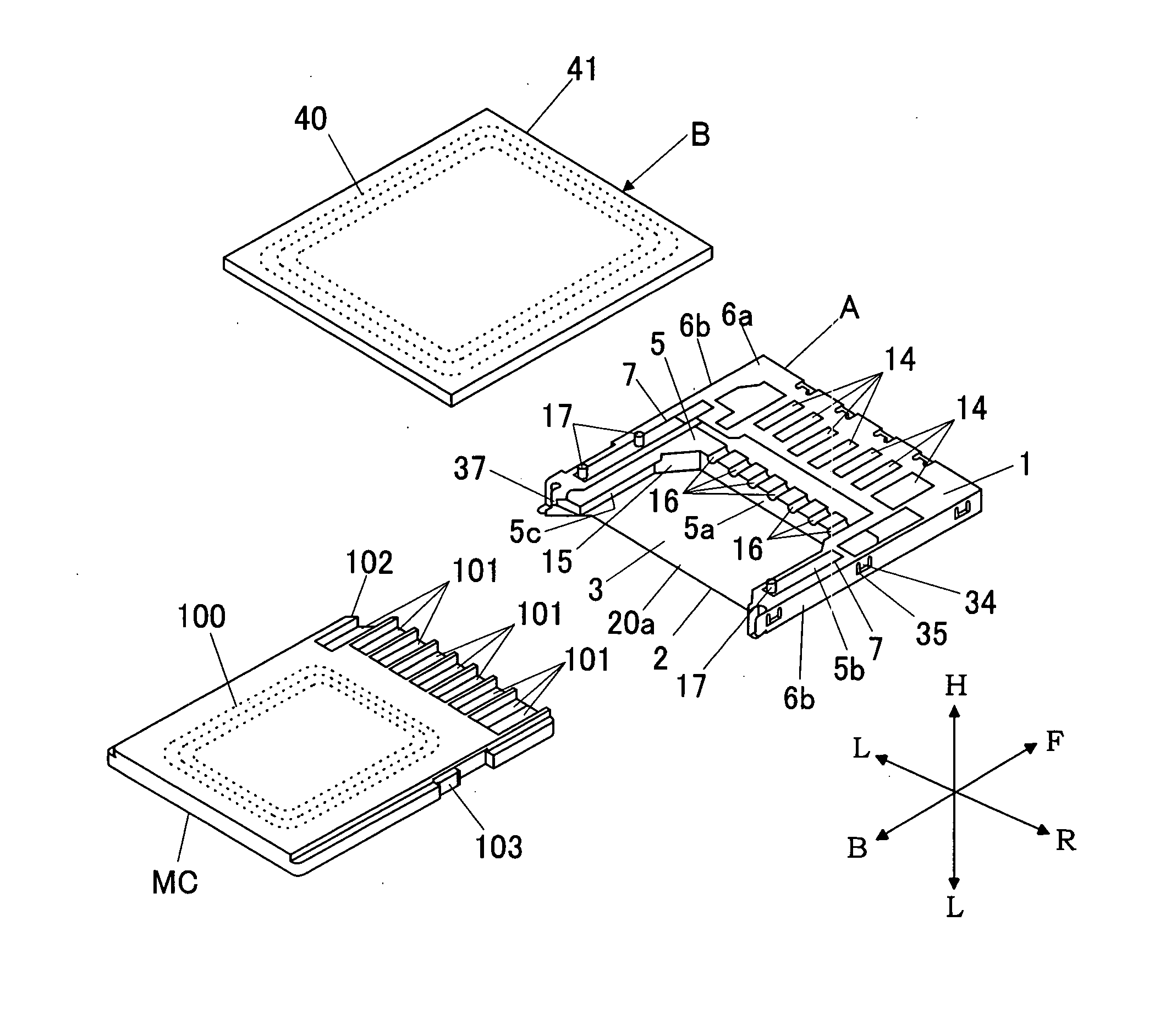
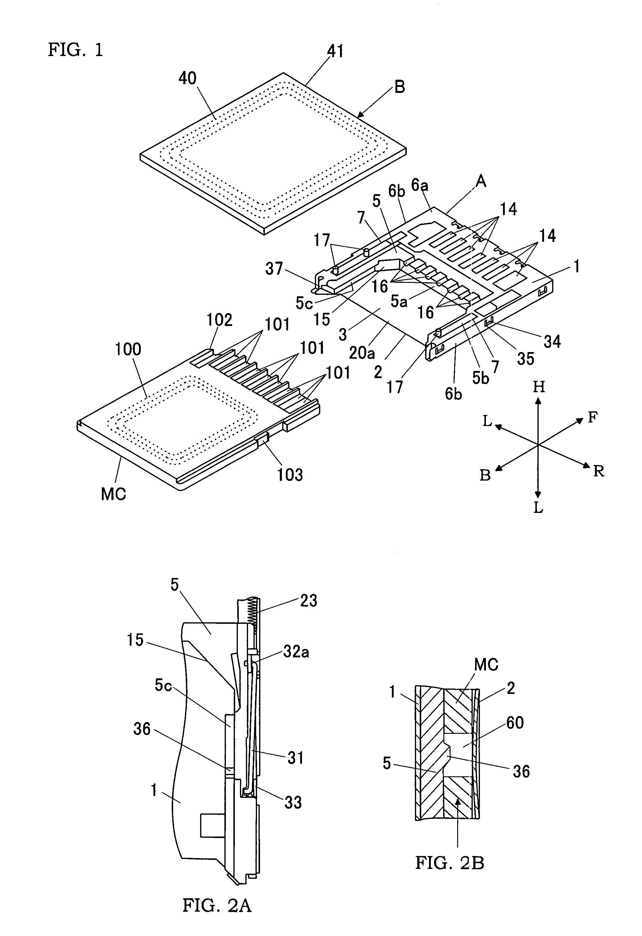
[0029]As shown in FIG. 1, a memory card MC used in this embodiment has a structure in which an antenna (a loop coil) 100 and an integrated circuit (IC) are built in a conventional SD Memory Card. The memory card MC is formed in a substantially rectangular thin plate, and has a plurality of (nine) connecting terminals 101 arranged in parallel at its front end. The numeral 102 designates an inclined edge formed at a corner of the front end of the memory card MC to prevent an improper insertion of the memory card. At the left lateral margin of the memory card MC, there is a locking notch (not shown) dented in a rectangular shape at a position backward from the inclined edge 102. In addition, the numeral 103 designates a write-protection switch provided at the right lateral margin of the memory card MC to be switchable between a data writable state and a write inhibitstate by manually sliding a knob back and forth.

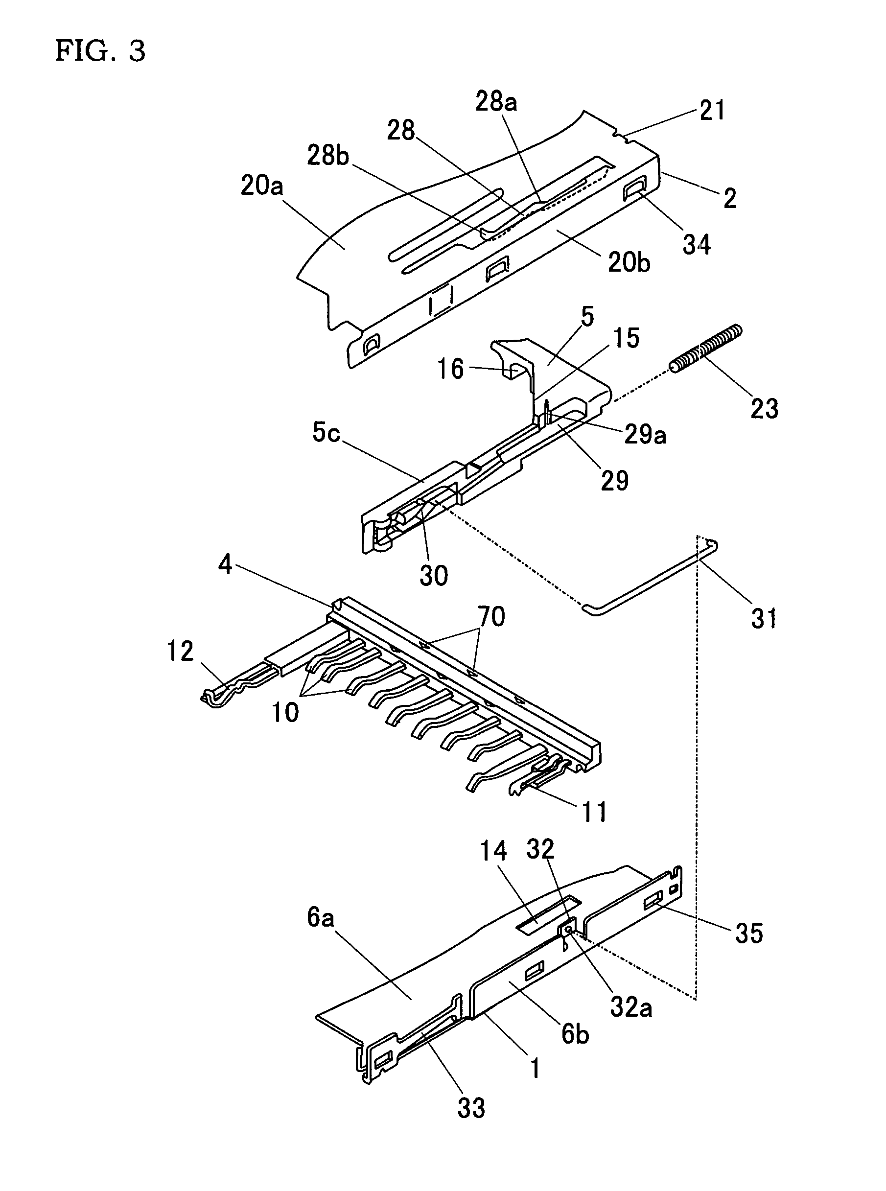
[0030]The memory card connector of this embodiment has a base body A, in ...

second embodiment

[0047]A memory card connector of this embodiment is substantially same as the first embodiment except for the following components. Therefore, the same reference numerals are added to the components common to the first embodiment, and the duplicate explanation is omitted.

[0048]As shown in FIG. 7, the connector of this embodiment is characterized by comprising an antenna block C having a carrier 41 formed in a rectangular plate, a secondary antenna 40 of a loop-like coil insert molded into the carrier, a pair of support members 80 for supporting the antenna block C to be slidable relative to a base body A along a direction (FB direction) of inserting and pulling out the memory card MC, and a pair of coil springs 24 for biasing the antenna block C in the direction of pulling out the memory card MC. In brief, in the first embodiment, since the slide member 5 is connected to the antenna block B, they are integrally slidable. On the other hand, in the present embodiment, the antenna bloc...


PUM


Abstract

A compact memory card connector with an extended communication distance is provided. This connector has a loading port at its one end, through which a memory card can be accommodated therein. The connector is equipped with a base made of an electrical insulating material, a plurality of contacts arranged on the base so as to electrically contact connecting terminals of the memory card inserted in the connector, and an antenna block, which houses a secondary antenna and is slidable in a direction of inserting the memory card into the connector.

Description

BACKGROUND OF THE INVENTION[0001]1. Field of the Invention[0002]The present invention relates to a connector, into which a memory card having a non-contact communication function can be inserted.[0003]2. Description of the Related Art[0004]In recent years, as a data storing means of electronic devices such as digital cameras and mobile phones, memory cards having a built-in nonvolatile memory such as flash memory, for example, “SD Memory Card” and “MultiMedia Card” are rapidly becoming pervasive. For example, a connector for this kind of memory card is disclosed in Japanese Patent Early Publication No. 2005-26016. This connector is formed with a housing having a loading port at its one end, through which the memory card can be inserted into the connector, a plurality of contacts configured to contact connecting terminals of the memory card inserted in the housing, a slide member that is slidable in the housing in synchronization with the memory card inserted from the loading port, a...

Claims


Application Information

Patent Timeline
Patent Type & Authority Patents(United States)
IPC IPC(8): H01R24/00
CPCG06K7/0047G06K7/10178G06K19/07G06K19/0723G06K19/07732H01Q1/22H01Q1/2275H01Q7/00H01R13/62983H01R12/714H01R12/7005H01R2201/02H01R12/72G06K17/00
Inventor TANAKA, HIROHISANAKAMURA, YUTAKA
Owner MATSUSHITA ELECTRIC WORKS LTD
Why Eureka
Try Eureka