Catalysts, reactors and methods of producing hydrogen via the water-gas shift reaction

a technology of catalysts and reaction reactions, applied in the direction of metal/metal-oxide/metal-hydroxide catalysts, combustible gas production, chemical production, etc., can solve the problems of catalyst deactivation, high reaction temperature, and both catalysts are not very active under their applicable conditions, and achieve the effect of superior results

Inactive Publication Date: 2009-02-10
BATTELLE MEMORIAL INST
View PDF30 Cites 0 Cited by
  • Summary
  • Abstract
  • Description
  • Claims
  • Application Information

AI Technical Summary

Benefits of technology

[0009]The invention also provides a reactor containing the inventive catalyst. Typically, the reactor contains a reactor inlet, a reaction chamber, and a reactor outlet. It is particularly advantageous for the reactor to also contain a microchannel heat exchanger in thermal contact with the reaction chamber. The microchannel heat exchanger enables rapid heat transfer from the reaction chamber thus allowing the inventive catalyst to operate at near isothermal and low temperature conditions to maximize CO2 selectivity while maintaining high conversions of carbon monoxide.
[0011]Various embodiments of the invention can provide numerous advantages including one or more of the following: high carbon monoxide conversions, high carbon dioxide selectivity, low methane selectivity, operation at short contact times, and low temperature operation.

Problems solved by technology

However, both catalysts are not very active under their applicable conditions as indicated by their operational contact times (contact time is defined as catalyst bed volume divided by volumetric gas feed flowrate at standard temperature and pressure) of several seconds.
Operating at shorter contact times with these commercial catalysts requires higher reaction temperatures, which not only accelerates catalyst deactivation due to metal sintering but also disfavors the thermodynamics of the WGSR, as mentioned above.

Method used


Image

  • Catalysts, reactors and methods of producing hydrogen via the water-gas shift reaction
  • Catalysts, reactors and methods of producing hydrogen via the water-gas shift reaction
  • Catalysts, reactors and methods of producing hydrogen via the water-gas shift reaction

Examples


example 1

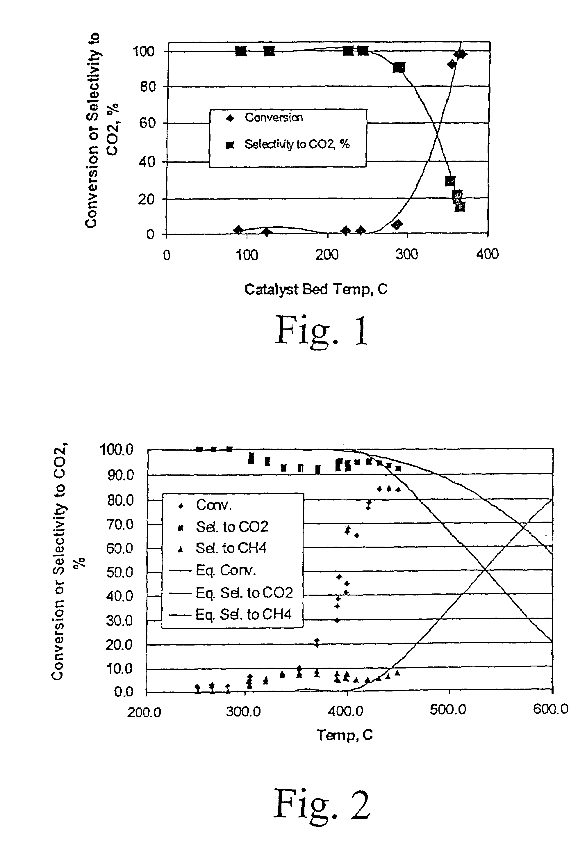
[0034]5 wt % Ru / ZrO2 catalyst was prepared by conventional incipient wetness impregnation. ZrO2 (6568-45-11F3 ⅛″ extrudates) was obtained from Engelhard, and ground and sieved into 70-100 mesh. Ru was impregnated onto the ZrO2 support to its incipient wetness point (0.4 cc / g) from an aqueous solution of RuCl3 hydrate (Aldrich, 99.98% ). The impregnated sample was set at room temperature for 30 min prior to drying under vacuum at 100° C. overnight. Finally, the catalyst was calcined under ambient conditions with a ramping rate of 5 C / min to 350° C. and isothermally held at that temperature for 1 h.

[0035]The water gas shift reaction was carried out in a conventional fixed-bed down flow reactor. The reactor used for powder testing has an inside diameter of 5 mm. Typical catalyst loading was 0.06 gram of 70-100 mesh particles. FIG. 1 shows an example of results from reaction of a gas mixture consisting of 8% CO, 7% CO2, 38% H2, and 47% H2O, over this powder 5 wt % Ru / ZrO2 catalyst, at a...

example 2

[0036]An improved powder catalyst, Ru / ZrO2 promoted with K, was also prepared using incipient wetness method. Specifically, a 0.5 wt % Ru-1.5% wtK / ZrO2 catalyst was prepared. ZrO2 (6568-45-11F3 ⅛′ extrudate) was obtained from Engelhard, and ground and sieved into 70-100 mesh. Ru and K were co-impregnated onto the ZrO2 support to its incipient wetness point (0.4 cc / g) from an aqueous solution of RuCl3 hydrate (Aldrich, 99.98% ) and KNO3 (Aldrich, 99.99% ). The impregnated sample was set at room temperature for 30 min prior to drying under vacuum at 100° C. overnight. Finally, the catalyst was calcined under ambient conditions with a ramping rate of 5C / min to 350° C. and isothermally held at that temperature for 1 h. Again, the water gas shift reaction was carried out in a conventional fixed-bed down flow reactor. The reactor used for powder testing has an inside diameter of 5 mm. Typical catalyst loading was 0.06 gram of 70-100 mesh particles. FIG. 2 shows an example of results from ...

example 3

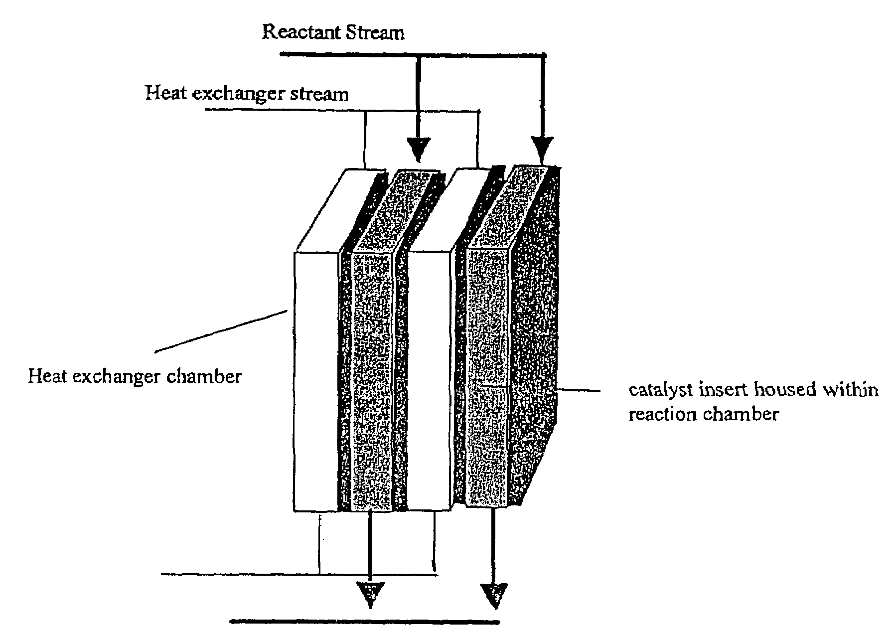
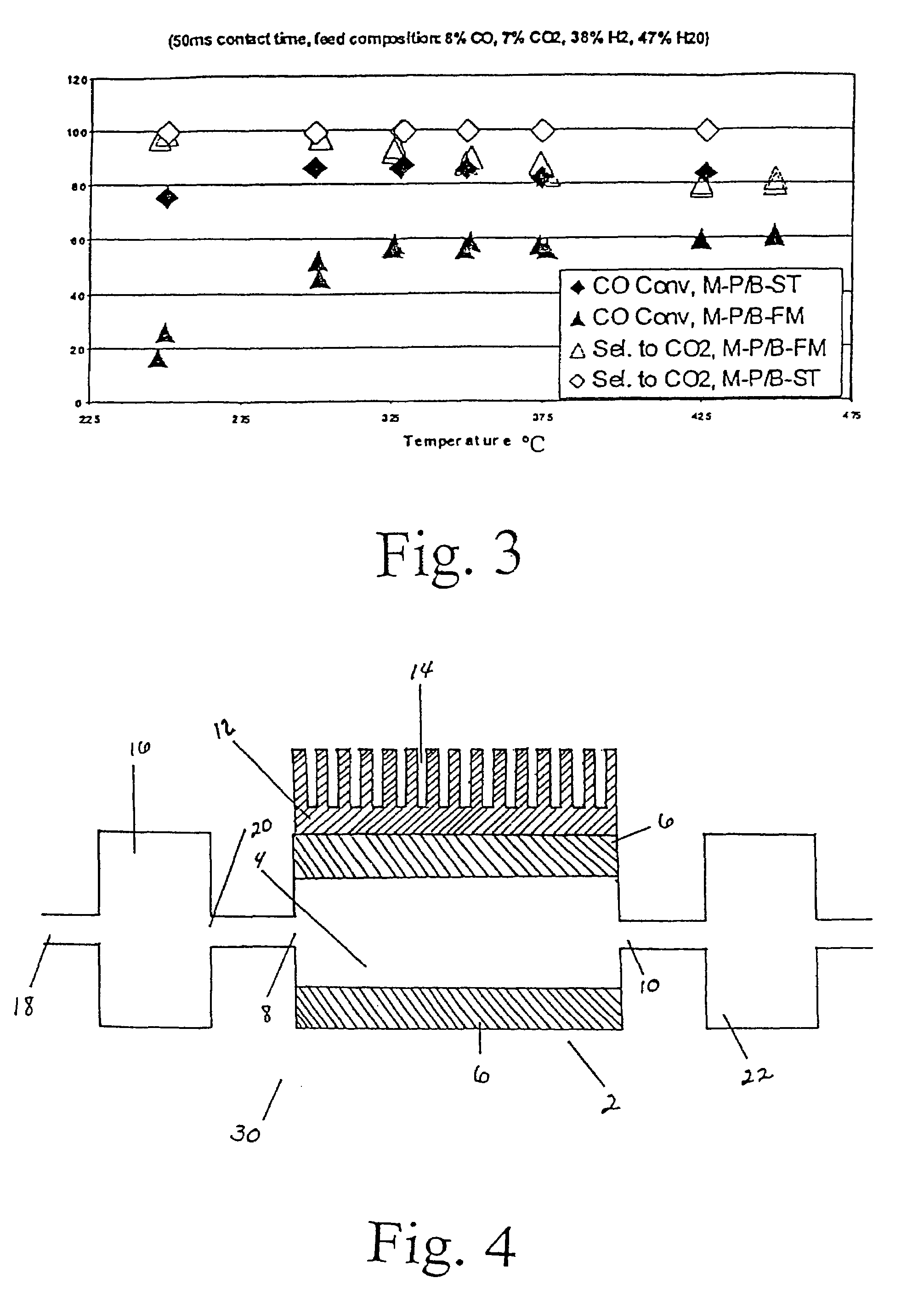
[0037]The powdered catalyst described in Example 2 was also investigated in various engineered forms. Experiments were conducted to demonstrate the present invention using 1 microchannel for the water gas shift reaction. The microchannel was placed within a tube furnace to provide the required preheat for the exothermic reaction. The microchannel was 5-cm long and 0.94-cm high. The width (or opening) of the microchannel was 0.0762-cm or 762-microns. In the case of felt-supported catalyst, 0.0222 g of powdered 0.5% Ru-1.5% K / ZrO2 catalyst described in Example 2 was coated on a metal felt of FeCrAl alloy obtained from Technetics, Deland, Fla. The dimensions of the felt are 1.27 cm in length, 0.94 cm in width, and 0.0254 cm in thickness. The porous structure contained a catalyst of 0.5% Ru-1.5% K / ZrO2 powdered catalyst that was prepared by 1) ball-milling the powdered catalyst 0.5% Ru-1.5% K / ZrO2 (using same method as described in Example 2) overnight; 2) slurry dip-coated on the FeCrA...


PUM

PropertyMeasurementUnit
pore sizeaaaaaaaaaa
temperatureaaaaaaaaaa
sizeaaaaaaaaaa

Abstract

The reaction of carbon monoxide with steam over an alkali-modified ruthenium-on-zirconia catalyst has been found to yield surprisingly high yields of hydrogen gas at relatively low temperatures. Catalyst structures, reactors, hydrogen production systems, and methods for producing hydrogen utilizing the alkali-modified ruthenium-on-zirconia catalyst are described. Methods of making catalysts are also described.

Description

RELATED APPLICATION[0001]The application is a divisional of Ser. No. 09 / 788,330 filed Feb. 16, 2001, now U.S. Pat. No. 6,652,830, incorporated herein by reference as if reproduced in full below.FIELD OF THE INVENTION[0002]The invention relates to catalysts, reactors and methods of producing hydrogen from the water gas shift reaction.INTRODUCTION[0003]Hydrogen gas (H2) can be readily produced from synthesis gas (syngas) by steam reforming, or partial oxidation, or autothermal reforming of hydrocarbons. Additional H2 is then produced by allowing syngas to react with steam according to the following exothermic water gas shift reaction (WGSR):CO+H2O=H2+CO2The thermodynamics of WGSR are well known. The equilibrium constant of this reaction increases as temperature deceases. Hence, to increase the production of H2, it is desirable to conduct the reaction at lower temperatures, which are also preferred from the standpoint of steam economy.[0004]Two types of commercially available WGSR cata...

Claims


Application Information

Patent Timeline
Patent Type & Authority Patents(United States)
IPC IPC(8): C10J3/84B01J23/00B01J19/00B01J23/58B01J35/10C01B3/16
CPCB01J19/0093B01J23/58B01J35/10C01B3/16B01J35/1076B01J2219/00835B01J2219/00844B01J2219/00873C01B2203/0205C01B2203/0283C01B2203/047C01B2203/066C01B2203/0883C01B2203/1064C01B2203/1082C01B2203/1094F28F2260/02Y02P20/52
Inventor WANG, YONGTONKOVICH, ANNA LEE Y.
Owner BATTELLE MEMORIAL INST
Why Eureka
Try Eureka