Image processing apparatus

a technology of image data and processing apparatus, applied in the direction of digital output to print units, instruments, data switching networks, etc., can solve the problems of exceeding the size limit, increasing the size of image data, and affecting so as to improve the efficiency of re-transmission of divided files and improve the efficiency of memory us

Inactive Publication Date: 2009-02-10
MINOLTA CO LTD
View PDF15 Cites 10 Cited by
  • Summary
  • Abstract
  • Description
  • Claims
  • Application Information

AI Technical Summary

Benefits of technology

[0016]On completion of transmission of a unit image, a file for transmission corresponding to the transmitted unit image is deleted, thereby enabling the memory to be efficiently used. Since a file for transmission corresponding to a unit image which has not been transmitted yet is held, even when any of the divided files is not delivered, it can be efficiently re-transmitted.
[0018]By dividing a file for transmission in the border of unit images, the file for transmission corresponding to the unit image can be efficiently deleted.
[0020]Since the file for transmission is held for predetermined time after the unit image is transmitted, even when any of the divided files is not delivered, it can be transmitted again more efficiently.
[0024]Therefore, an object of the invention is to improve the efficiency of use of a memory at the time of transmitting an image.
[0025]Another object of the invention is to improve the efficiency of re-transmission of a divided file when the divided file is not transmitted.

Problems solved by technology

The size of image data is increasing and, particularly, the size of color image data is enormous which is about 60 MB per image and may exceeds the size limit for E-mail set by a mail server.
The Internet is an infrastructure which does not guarantee data transmission to a destination and in which transmission data may be dropped out.
In such a manner, an error in E-mail transmission is detected.
However, some MFPs do not have a memory capacity sufficient to hold all of divided mails (image data) transmitted.
It is troublesome for the user to re-transmit the image by confirming a not-delivered unit image, setting the original, and the like.

Method used


Image

  • Image processing apparatus
  • Image processing apparatus
  • Image processing apparatus

Examples


first embodiment

Network System

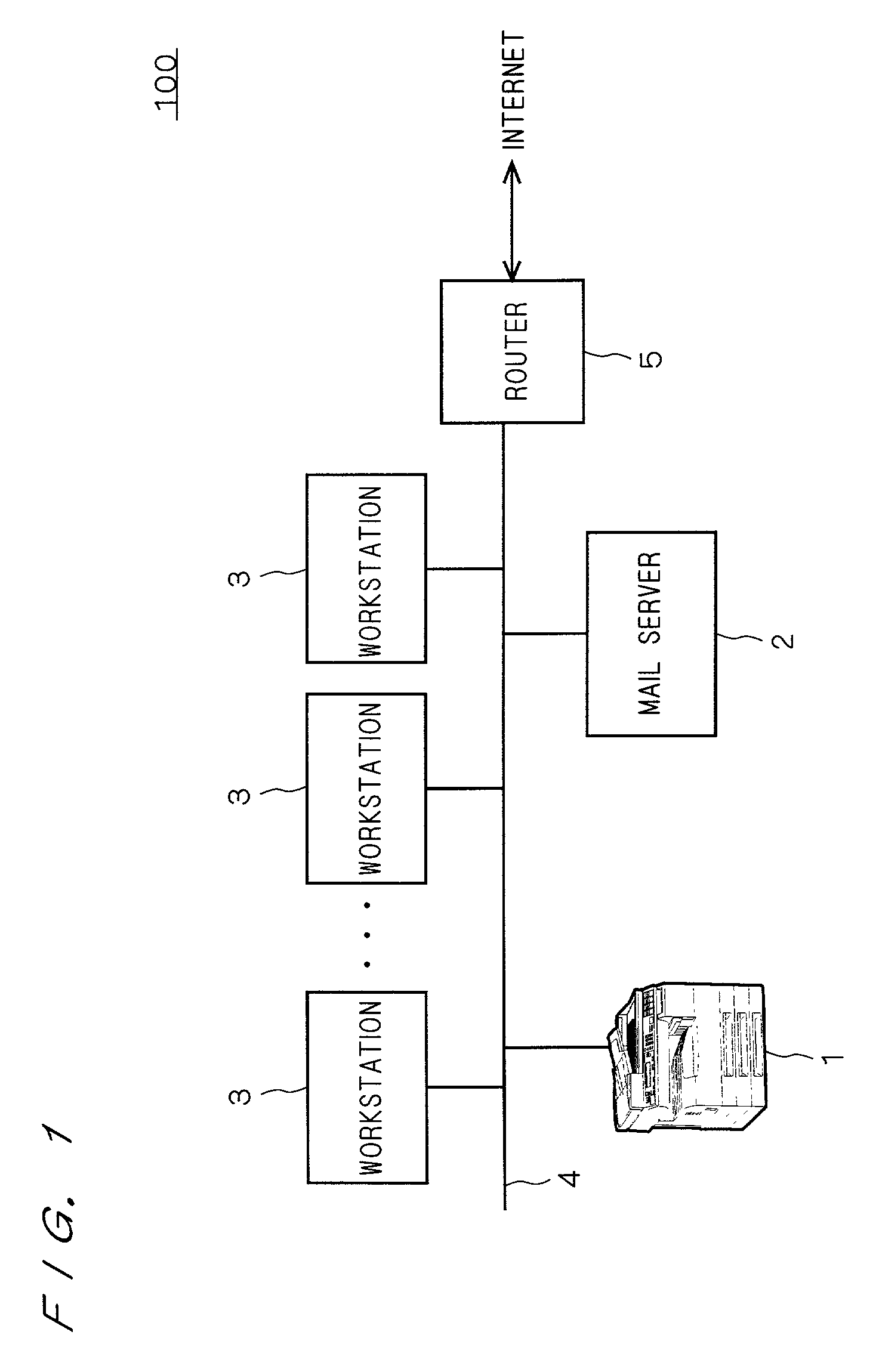
[0040]FIG. 1 shows an example of a network system applied to a preferred embodiment of the invention.

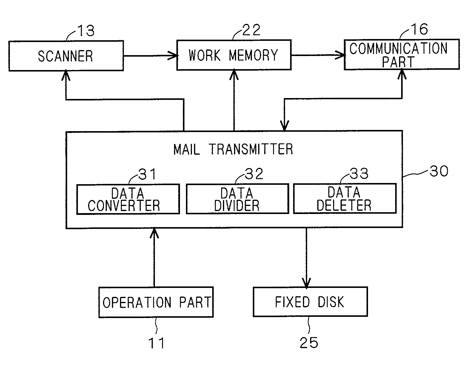
[0041]As shown in the drawing, a network system 100 has an MFP 1 as an image processing apparatus according to the preferred embodiment of the invention, a mail server 2, and a plurality of workstations 3 each connected to a local area network (hereinbelow, “LAN”) 4. The LAN 4 is also connected to an external network such as the Internet via a router 5.

[0042]The mail server 2 provides known services of collection and distribution of E-mail. The workstation 3, MFP 1, and the like connected to the LAN 4 transmit / receive E-mail to / from an external device connected to a network such as the LAN 4 and the Internet via the mail server 2. For example, in the case of transmitting E-mail from the MFP 1, first, E-mail is transmitted to the mail server 2. Further, the E-mail transmitted to the mail server 2 is received by an external device at a transmission destination via a plura...

second preferred embodiment

[0086]A second preferred embodiment of the invention will now be described. Although the divided files are not always divided in the borders of unit images in the first preferred embodiment, in the second preferred embodiment, the divided files are positively divided in the borders of the unit images. The configuration of the image processing apparatus in the preferred embodiment is similar to that in any of FIGS. 2 to 4. The flow of the E-mail transmitting process is also similar to that shown in FIG. 7. Since only the E-mail dividing method in the data divider 32 is different, only this part will be described.

[0087]The data divider 32 of the second preferred embodiment does not simply divide ASCII data of a plurality of unit images in one file every predetermined reference data size. When a border between unit images exists, the data is always divided in the border. The division is made by confirming the header information and footer information existing in borders of the unit ima...


PUM


Abstract

An MFP can transmit image data read by a scanner by attaching it to E-mail. At the time of transmission, the image data input by the scanner and stored in a work memory is converted into mail data so as to be transmitted by E-mail, and the mail data is stored again into the work memory. The mail data is divided every predetermined reference data size into divided files which are sequentially transmitted as divided mails. When completion of transmission of divided mails corresponding to a unit image is confirmed, the image data and mail data of the unit image are eliminated from the work memory. By sequentially performing such a process, the memory use efficiency can be improved while holding image data of a unit image which has not been transmitted yet.

Description

[0001]This application is based on application No. 2001-090476 filed in Japan, the contents of which are hereby incorporated by reference.BACKGROUND OF THE INVENTION[0002]1. Field of the Invention[0003]The present invention relates to a technique of transmitting image data.[0004]2. Description of the Background Art[0005]As one of conventional image processing apparatuses capable of performing communication through a network, an MFP (Multi Function Peripheral) is known. The MFP is a composite device having the functions of scanner, copier, printer, facsimile, and the like. Further, the MFP can attach an image read by the scanner function or the like to electronic mail (E-mail) and directly transmit the resultant to an MFP or the like at the destination via a network such as the Internet or a LAN.[0006]In the case of transmitting E-mail from a transmission source to a destination, it is transmitted via a plurality of mail servers. In each mail server, a system administrator sets a siz...

Claims


Application Information

Patent Timeline
Patent Type & Authority Patents(United States)
IPC IPC(8): G06F3/12G06K15/00H04M11/00H04N1/00H04N1/387G06F13/00H04L12/58H04N1/21H04N1/32
CPCH04L12/58H04N1/00209H04N1/00212H04N1/32368H04N2201/0025H04N2201/0068H04N2201/0094H04N2201/3295H04L51/23H04L51/00
Inventor ISHIKAWA, ATSUSHI
Owner MINOLTA CO LTD
Why Eureka
Try Eureka