
Servo writing a disk drive using a secondary actuator to control skew angle

a technology of servo writing and disk drives, applied in the field of disk drives, can solve the problems of radial offset between read and write elements in magnetoresistive (mr) heads, high cost of each servo writer and clean room, and inability to write disk drives at the same time, and achieve the effect of constant skew angle and constant track density

Inactive Publication Date: 2009-02-10
WESTERN DIGITAL TECH INC
View PDF35 Cites 119 Cited by
  • Summary
  • Abstract
  • Description
  • Claims
  • Application Information

AI Technical Summary

Benefits of technology

[0023]In yet another embodiment, the control circuitry adjusts a control signal applied to the secondary actuator to maintain a substantially constant skew angle while moving the head radially across the disk to achieve a substantially

Problems solved by technology

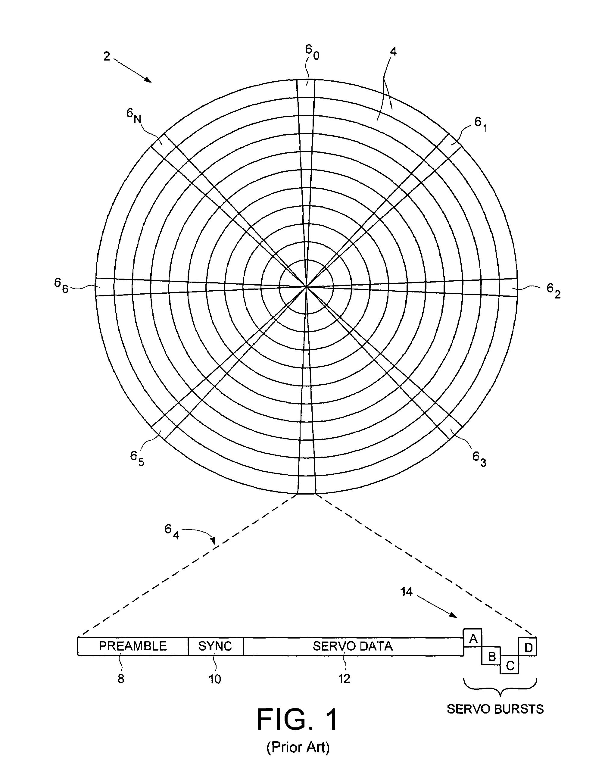
There are certain drawbacks associated with using external servo writers to write the embedded servo sectors 6 during manufacturing.
Further, the manufacturing throughput is limited by the number of servo writers available, and the cost of each servo writer and clean room becomes very expensive to duplicate.
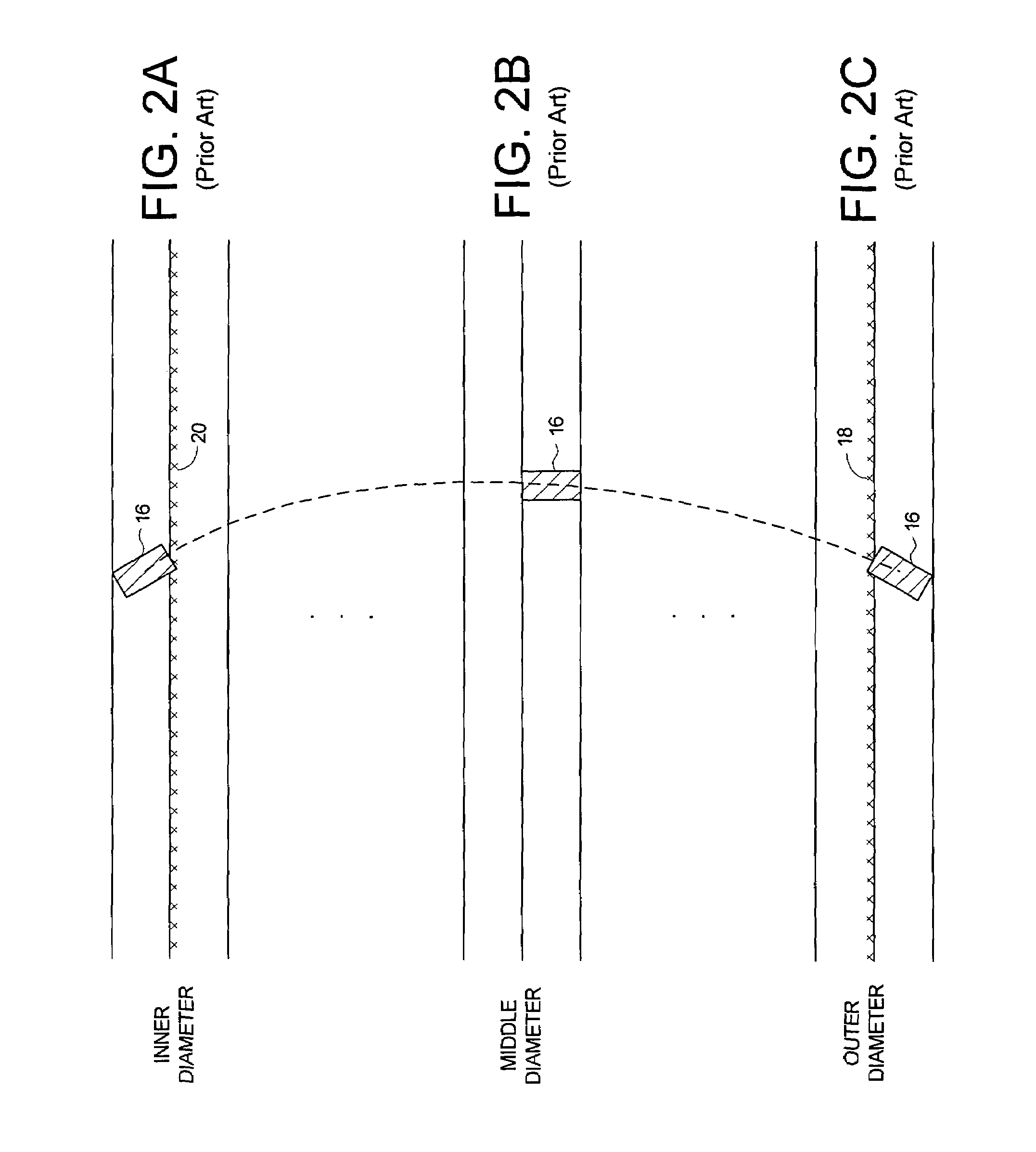
The radial offset between the read and write elements in magnetoresistive (MR) heads presents a problem when using the prior art technique of propagating servo sectors from track to track.
This lag renders it difficult for the read element to read the previously written servo track while writing the next servo track using the write element.
However, the geometry of the trapezoidal shape varies between each disk drive due to tolerances in manufacturing the head, resulting in undesirable seams in the servo wedges for some percentage of the disk drives.
In addition, manufacturing the write pole with a trapezoidal shape increases the manufacturing cost of the head, as well as reduces the surface area of the write pole leading to an undesirable decrease in the strength of the magnetic write flux.
A problem with this technique, however, is the seam created near the middle diameter of the disk where the two segments of a servo wedge “meet”.
This problem is exacerbated due to the disk expanding during the servo writing operation requiring a predetermined margin (wider seam) to account for the worst case deviation in the expansion.

Method used


Image

  • Servo writing a disk drive using a secondary actuator to control skew angle
  • Servo writing a disk drive using a secondary actuator to control skew angle
  • Servo writing a disk drive using a secondary actuator to control skew angle

Examples


Embodiment Construction

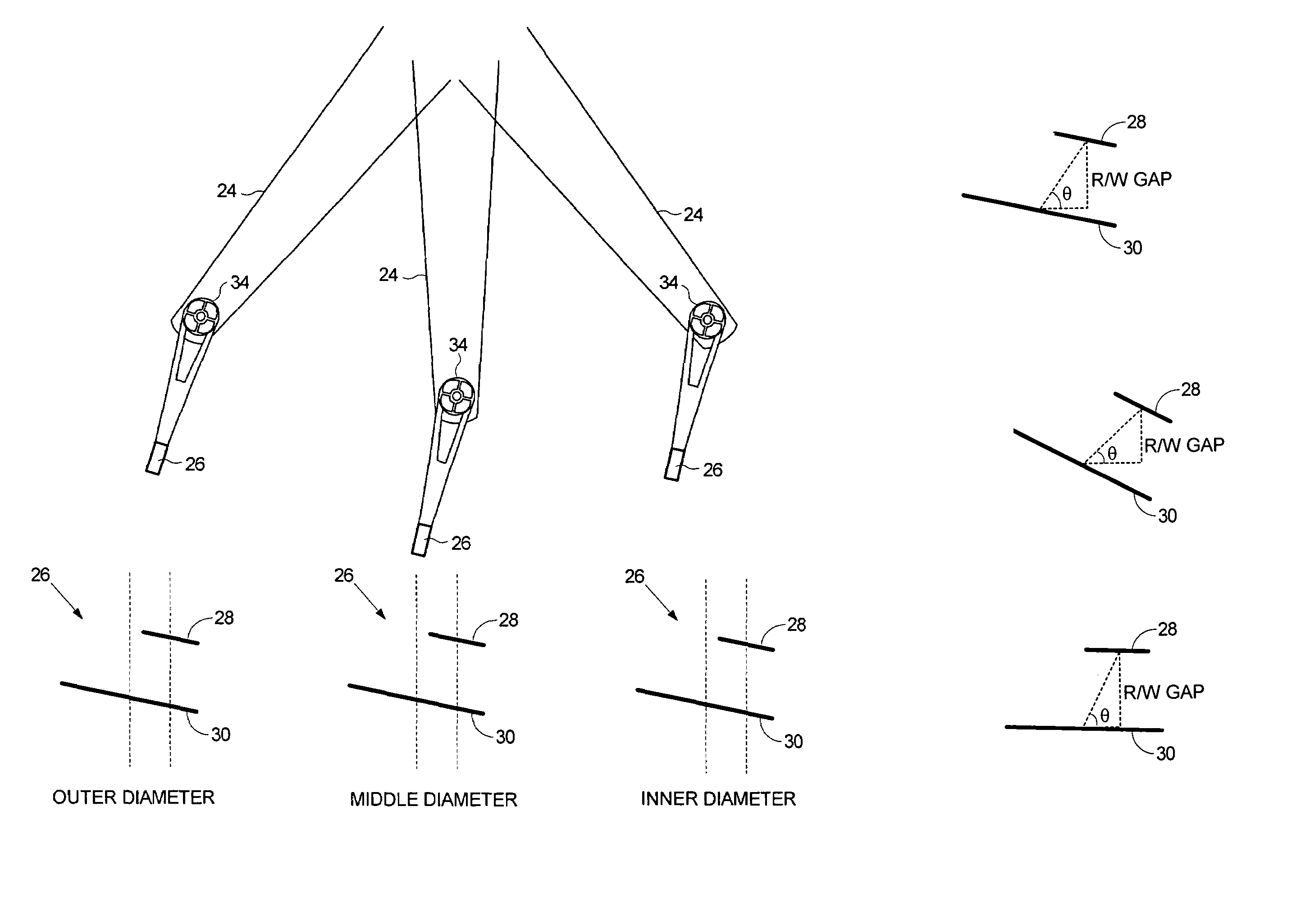
[0036]FIG. 3A shows a disk drive comprising a disk 22, an actuator arm 24, and a head 26 coupled to a distal end of the actuator arm 24, wherein the head 26 comprises a read element 28 and a write element 30 (FIG. 3B). A voice coil motor (VCM) 32 rotates the actuator arm 24 about a pivot to actuate the head 26 radially over the disk 22, and a secondary actuator 34 adjusts a skew angle of the head 26. Control circuitry 36 writes a plurality of servo sectors 380-38N to the disk 22 to define a plurality of data tracks 40. The control circuitry 36 controls the VCM 32 to move the head 26 radially across the disk 22, and controls the secondary actuator 34 to achieve a desired skew angle for the head 26 while using the write element 30 to write the servo sectors 380-38N to the disk 22.

[0037]The disk drive in the embodiment of FIG. 3A comprises a read channel 42 for processing the read signal 44 emanating from the head 26. In one embodiment, the read channel 42 comprises suitable circuitry ...


PUM


Abstract

A method of servo writing a plurality of servo sectors to a disk of a disk drive to define a plurality of data tracks is disclosed. The disk drive comprises the disk, an actuator arm, a head coupled to a distal end of the actuator arm, wherein the head comprises a read element and a write element. A voice coil motor (VCM) rotates the actuator arm about a pivot to actuate the head radially over the disk, and a secondary actuator adjusts a skew angle for the head while using the write element to write the servo sectors to the disk.

Description

CROSS REFERENCE TO RELATED APPLICATIONS AND PATENTS[0001]This application is related to co-pending U.S. patent application Ser. No. 10 / 971,215 entitled “METHOD OF OPERATING A DISK DRIVE INCLUDING ROTATING A PERPENDICULAR WRITE HEAD TO REDUCE A DIFFERENCE BETWEEN SKEW AND TAPER ANGLES, AND A DISK DRIVE” filed on Oct. 22, 2004, the disclosure of which is incorporated herein by reference.BACKGROUND OF THE INVENTION[0002]1. Field of the Invention[0003]The present invention relates to disk drives. More particularly, the present invention relates to servo writing a disk drive using a secondary actuator to control skew angle.[0004]2. Description of the Prior Art[0005]Disk drives for computer systems comprise a disk for storing data and a head actuated radially over the disk for writing data to and reading data from the disk. To effectuate the radial positioning of the head over the disk, the head is connected to the distal end of an actuator arm which is rotated about a pivot by a rotary a...

Claims


Application Information

Patent Timeline
IPC IPC(8): G11B21/02
CPCG11B5/4826G11B5/5552G11B5/59633G11B5/59638
Inventor MCNAB, ROBERT J.WEERASOORIYA, SIRI S.
Owner WESTERN DIGITAL TECH INC
Learn More