Twist drill

a twisting drill and drill bit technology, applied in the direction of twisting drills, manufacturing tools, wood boring tools, etc., can solve the problems of long time required for drilling through holes and called chatter, and achieve the effects of small force generated during drilling so as to lift the workpiece, good cutting ability, and high quality drilling

Inactive Publication Date: 2011-04-07
SUMITOMO ELECTRIC HARDMETAL CORP
View PDF3 Cites 25 Cited by
  • Summary
  • Abstract
  • Description
  • Claims
  • Application Information

AI Technical Summary

Benefits of technology

[0015]In the drill according to the present invention, the secondary cutting edge has a skew angle in the range of ±5° with respect to the rotation axis. Therefore, the secondary cutting edge is short, and a force generated during drilling so as to lift the workpiece is small. As a result, even when the workpiece is a thin plate that cannot be tightly fixed, high quality drilling can be performed without causing chatter.
[0016]In the drill, the rake face of the secondary cutting edge is included in the flute face of the helical flute, so that the rake angle of the secondary cutting edge is not small. Depending on the shape of the helical flute, the rake angle of the secondary cutting edge is larger than that of the existing drill illustrated in FIG. 8, whereby a good cutting ability is realized. Thus, fuzzing when drilling a fiber-reinforced composite material is suppressed, and cutting force is decreased.
[0017]Moreover, the amount of work and time for manufacturing the drill do not increase because it is not necessary to form a flat rake face.

Problems solved by technology

However, a drill having a small point angle often causes so-called chatter, because such a drill has a long cutting edge.
In particular, a long time is required for drilling a through-hole, because it is necessary to deeply insert the drill.

Method used


Image

  • Twist drill
  • Twist drill
  • Twist drill

Examples


example 1

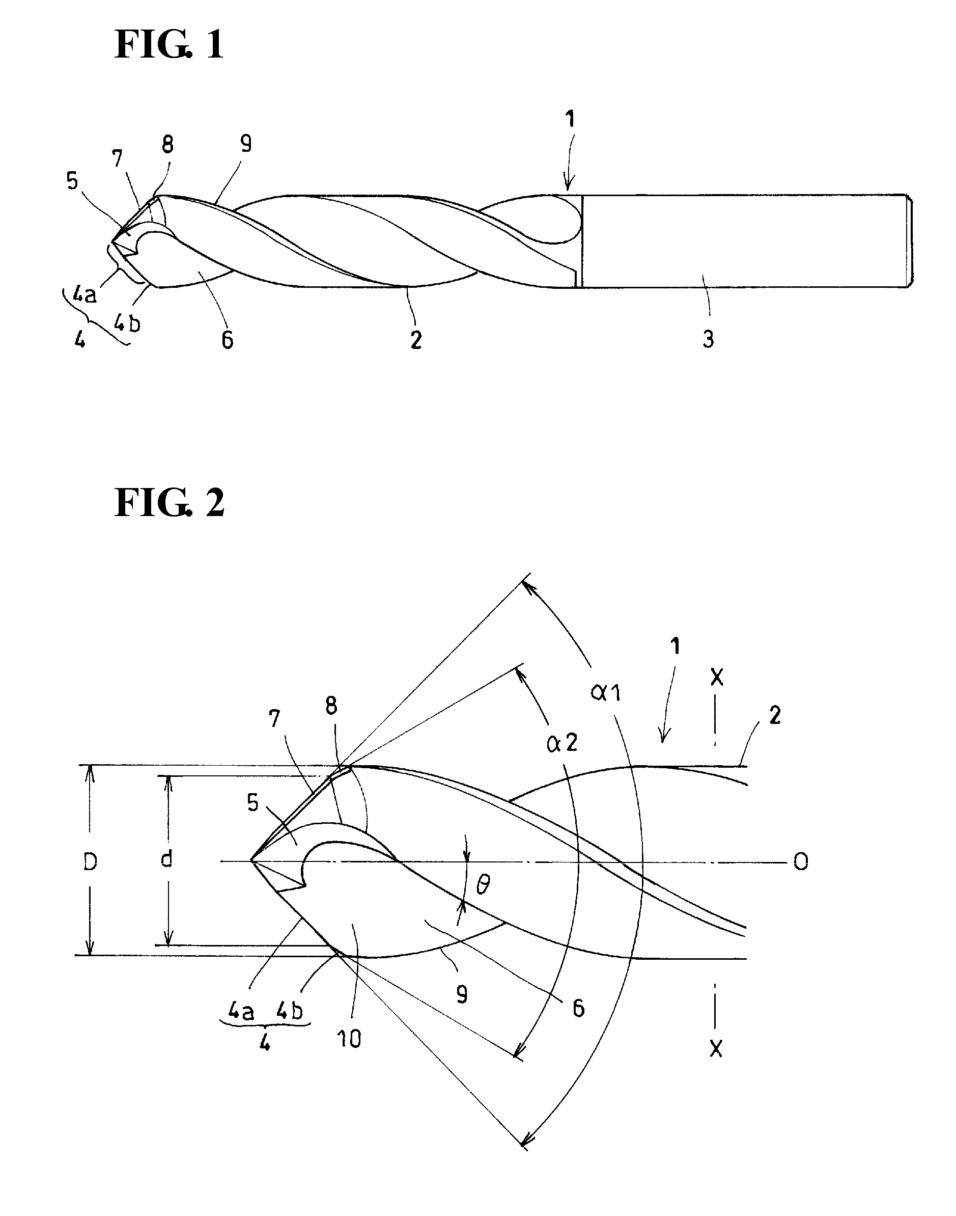
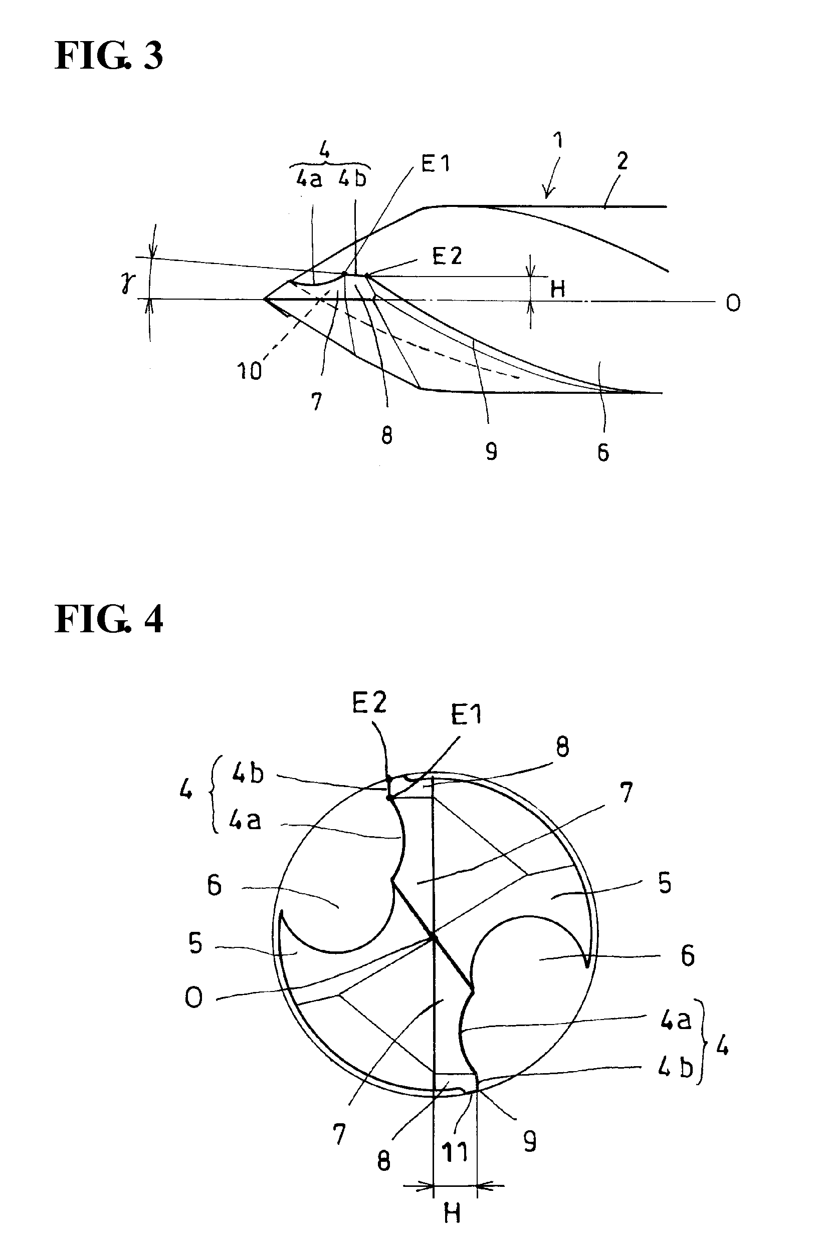
[0037]The influence of the skew angle γ of the secondary cutting edge with respect to the rotation axis on the drilling quality of the double-angle drill was examined. The specifications of the drill used in this test were as follows: the drill diameter D=φ10 mm, the point angle of primary cutting edge was 120°, the point angle of secondary cutting edge was 60°, the diameter of outer end portion of primary cutting edge d=0.9D, and the skew angle γ of the secondary cutting edge was varied as illustrated in Table I.

[0038]A CFRP plate having a thickness of 3 mm was used as a workpiece. The cutting conditions were such that the cutting speed Vc=100 m / min and the feed f=0.05 mm / rev. Table I lists the result of the experiment.

[0039]In the row for chatter in Table I, “+” represents “chatter did not occur”, “±” represents “slight chatter occurred”, and “−” represents “chatter occurred”. In the row for fuzzing, “+” represents “fuzzing did not occur and the quality of the inner surface of a d...

example 2

[0041]Next, the influence of a difference in the point angle α2 of the secondary cutting edge of the double-angle drill on the quality of drilling and the tip wear was examined. The specifications of the drill used in this test were as follows: the drill diameter D=φ6 mm, the point angle of primary cutting edge α1=140°, and the diameter of the drill at the outer end of primary cutting edge d=0.83D.

[0042]A CFRP plate having a thickness of 10 mm was used as a workpiece. The cutting conditions were such that the cutting speed Vc=100 m / min and the feed f=0.05 mm / rev. Table II lists the result of the experiment.

[0043]In the row for fuzzing in Table II, “+” represents “fuzzing did not occur and the quality of the inner surface of a drilled hole was excellent” and “−” represents “fuzzing occurred and the quality of the inner surface of a drilled hole was poor”. The tip wear was evaluated after drilling 500 holes. The tip wear amount in the cells of evaluation represents the maximum flank f...


PUM

PropertyMeasurementUnit
skew angleaaaaaaaaaa
helix angleaaaaaaaaaa

Abstract

Provided is a double-angle twist drill that increases the quality of drilling without increasing the amount of manufacturing work or the like. A secondary cutting edge 4b is substantially parallel to the rotation axis O of the drill, and at least a rake face 10 of the secondary cutting edge is included in the flute face of a helical flute 6. A part of the flute face of the helical flute that is located along a leading edge 9 is convexly curved with respect to the normal direction of rotation of the drill, so that the secondary cutting edge 4b having a small skew angle with respect to the rotation axis can be formed as a ridge at which the flute face intersects a second flank face.

Description

TECHNICAL FIELD[0001]The present invention relates to a double-angle twist drill including a cutting edge having a primary cutting edge that is disposed adjacent to the rotation center and a secondary cutting edge (peripheral cutting edge) that is connected to an outer end of the primary cutting edge, the primary and secondary cutting edges having different point angles.BACKGROUND ART[0002]When drilling a fiber-reinforced composite material such as a carbon fiber reinforced plastic (CFRP), a drill having a smaller point angle causes a smaller degree of fuzzing of reinforcing fibers of a workpiece. However, a drill having a small point angle often causes so-called chatter, because such a drill has a long cutting edge. In particular, a long time is required for drilling a through-hole, because it is necessary to deeply insert the drill.[0003]A double-angle twist drill has a primary cutting edge and a secondary cutting edge that have different point angles so as to limit the length of ...

Claims


Application Information

Patent Timeline
Patent Type & Authority Applications(United States)
IPC IPC(8): B23B51/02
CPCB23B51/02B23B2226/27Y10T408/9097B23B2251/085B23B2251/14B23B2251/04B23B2226/275
Inventor NAKAMURA, NAOHIROABE, MAKOTO
Owner SUMITOMO ELECTRIC HARDMETAL CORP
Why Eureka
Try Eureka