
10KV power transmission line foundation excavation device

A transmission line, basic technology, applied in the direction of drilling, drilling equipment, drilling equipment and methods with mechanical conveying devices, etc. Low, waste soil falling and other problems, to avoid the uplift of the top of the drill hole, avoid repeated drilling operations, and ensure the effect of cleanliness

Pending Publication Date: 2021-05-14
杨泽昆
View PDF10 Cites 1 Cited by
  • Summary
  • Abstract
  • Description
  • Claims
  • Application Information

AI Technical Summary

Problems solved by technology

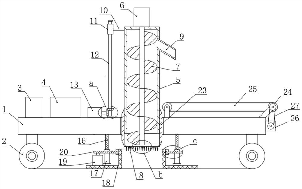
[0004] The excavation device in the prior art still has the following disadvantages when in use. When the excavation device is excavating, a large amount of waste soil will be generated, and the waste soil will be scattered around the borehole, which cannot be cleaned in time, which will inevitably cause waste. The soil falls into the borehole; at the same time, the inner wall of the borehole has low flatness and compaction, and there is a defect that the borehole collapses when the compactness of the soil itself is low. In addition, the soil on the top of the borehole will The crushing operation causes the top of the borehole to bulge, which affects the flatness and aesthetics of the top of the borehole. Therefore, the present invention re-proposes a 10KV power transmission line foundation excavation device.

Method used


Image

  • 10KV power transmission line foundation excavation device
  • 10KV power transmission line foundation excavation device
  • 10KV power transmission line foundation excavation device

Examples


Embodiment Construction

[0035] The following will clearly and completely describe the technical solutions in the embodiments of the present invention with reference to the accompanying drawings in the embodiments of the present invention. Obviously, the described embodiments are only some, not all, embodiments of the present invention.

[0036] In describing the present invention, it should be understood that the terms "upper", "lower", "front", "rear", "left", "right", "top", "bottom", "inner", " The orientation or positional relationship indicated by "outside", etc. is based on the orientation or positional relationship shown in the drawings, and is only for the convenience of describing the present invention and simplifying the description, rather than indicating or implying that the referred device or element must have a specific orientation, so as to Specific orientation configurations and operations, therefore, are not to be construed as limitations on the invention.

[0037] refer to Figure ...


PUM


Abstract

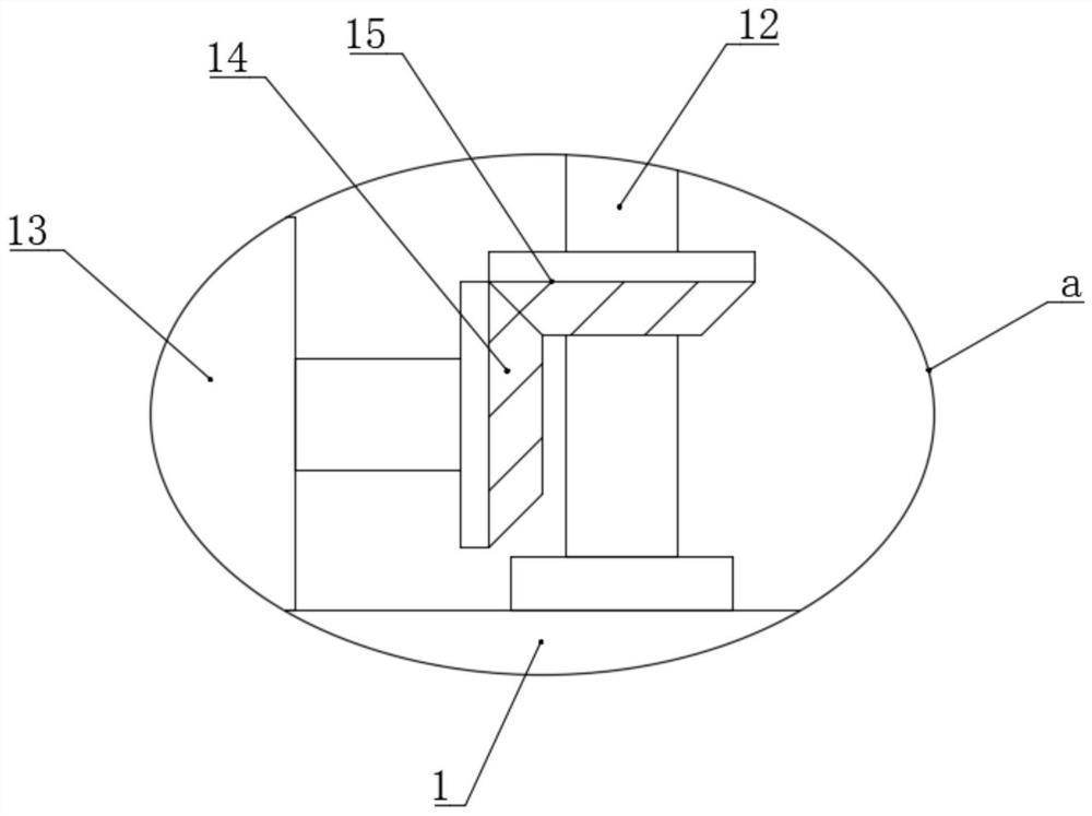
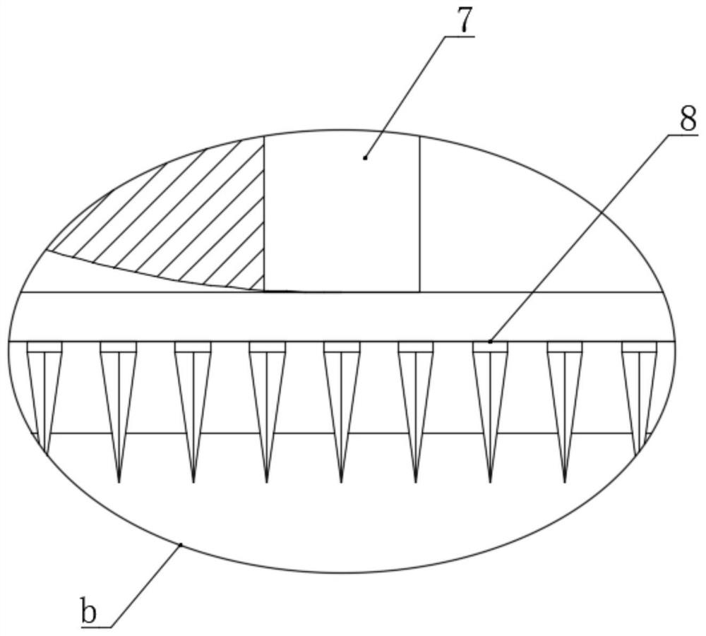
The invention discloses a 10KV power transmission line foundation excavation device, and belongs to the technical field of power transmission line foundation excavation. The 10KV power transmission line foundation excavation device comprises a base plate, universal wheels are installed on the bottom wall of the base plate, a through hole is formed in the center position of the base plate in a penetrating manner, an excavation pipe and an hole expanding device are arranged in the through hole, the bottom of the excavation pipe is open, and a spiral earth cutting device and a crusher are rotationally installed inside the excavation pipe, and the crusher is installed at the bottom end of the spiral earth cutting device. According to the 10KV power transmission line foundation excavation device, high-efficiency and high-quality drilling operation can be achieved, waste soil generated during drilling can be cleared away in time to be far away from a drill hole, so that the waste soil cannot fall into the drill hole again, cleanliness of the drill hole is guaranteed, the top of the drill hole can be compacted, the top of the drill hole is prevented from protruding, the top flatness of the drill hole is improved, in addition, the inner wall of the drill hole can be expanded and extruded, the flatness and compactness of soil on the inner wall of the drill hole are improved, the soil in the drill hole is prevented from collapsing, and the integrity of the drill hole is guaranteed.

Description

technical field [0001] The invention relates to the technical field of power transmission line foundation excavation, in particular to a 10KV power transmission line foundation excavation device. Background technique [0002] With the rapid development of the economy, my country's construction engineering industry has also developed rapidly. The development of the construction engineering industry directly promotes the rapid development of construction machinery technology and equipment. Various types of construction machinery emerge in endlessly and are used in various construction fields; The excavation of the transmission line foundation has its own special requirements for the drill bit and drilling depth. The cost of large-scale construction machinery is too high, and the small ground drilling machine cannot meet the requirements of the line foundation for the pit depth and pit width. [0003] After retrieval, Chinese Patent No. CN 109252809 B discloses a 10KV power tran...

Claims


Application Information

Patent Timeline
IPC IPC(8): E21B7/02E21B7/00E21B7/30E21B12/00
CPCE21B7/02E21B7/005E21B7/003E21B7/30E21B12/00
Inventor 杨泽昆郝衍蒙侯志涛
Owner 杨泽昆
Learn More