
Main mirror with pivot connection

a technology for rearview mirrors and pivot connections, which is applied in the field of pivot connections for rearview mirrors, can solve the problems of increasing the complexity of assembly operation, requiring additional parts, and adding cost and weight to the mirrors

Inactive Publication Date: 2009-02-17
MAGNA MIRRORS OF AMERICA INC
View PDF47 Cites 30 Cited by
  • Summary
  • Abstract
  • Description
  • Claims
  • Application Information

AI Technical Summary

Problems solved by technology

While the aforementioned assembly satisfactorily enables pivoting of the reflective element assembly relative to the base, it requires the use of a spring and friction nut, which increases the complexity of the assembly operation, requires additional parts which add cost and weight to the mirror, and may require special tools to assemble.

Method used


Image

  • Main mirror with pivot connection
  • Main mirror with pivot connection
  • Main mirror with pivot connection

Examples


first embodiment

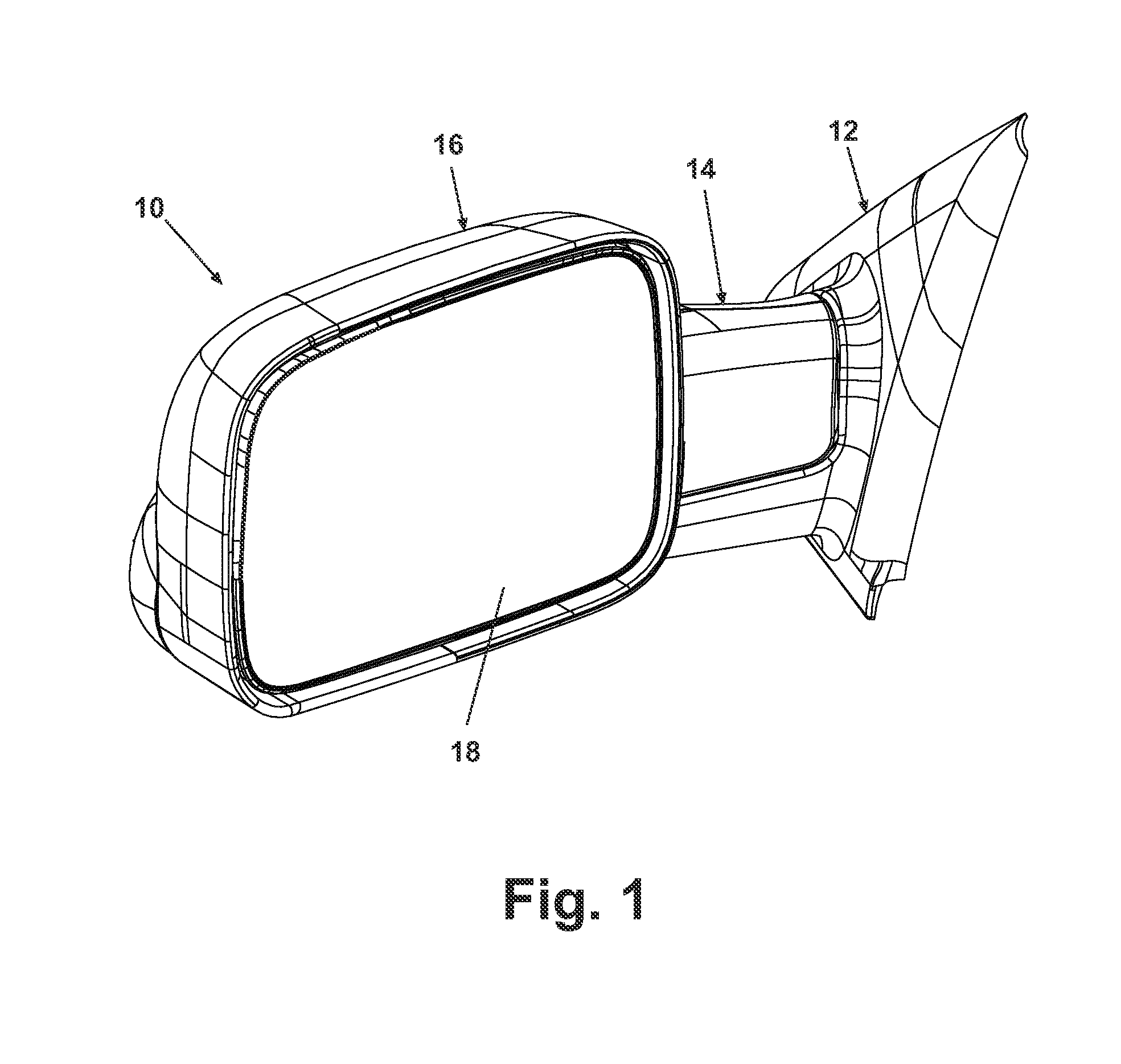
[0034]Referring now to the Figures, and in particular to FIG. 1, an external vehicular mirror system 10 comprising a pivot connection according to the invention is illustrated. The mirror system 10 comprises a base 12 adapted for mounting to the exterior of a motor vehicle, a support arm 14 adapted for pivoting movement relative to the base 12, and a reflective element assembly 16 attached to and supported by the support arm 14. The reflective element assembly 16 comprises a well-known reflective element 18 for providing the driver of the motor vehicle with a rearward view.

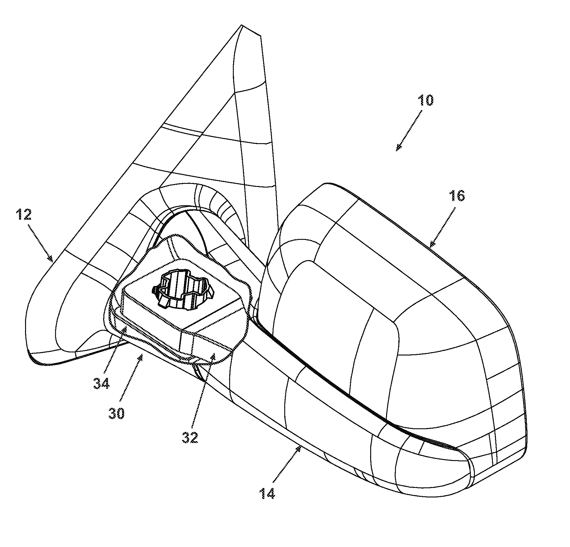
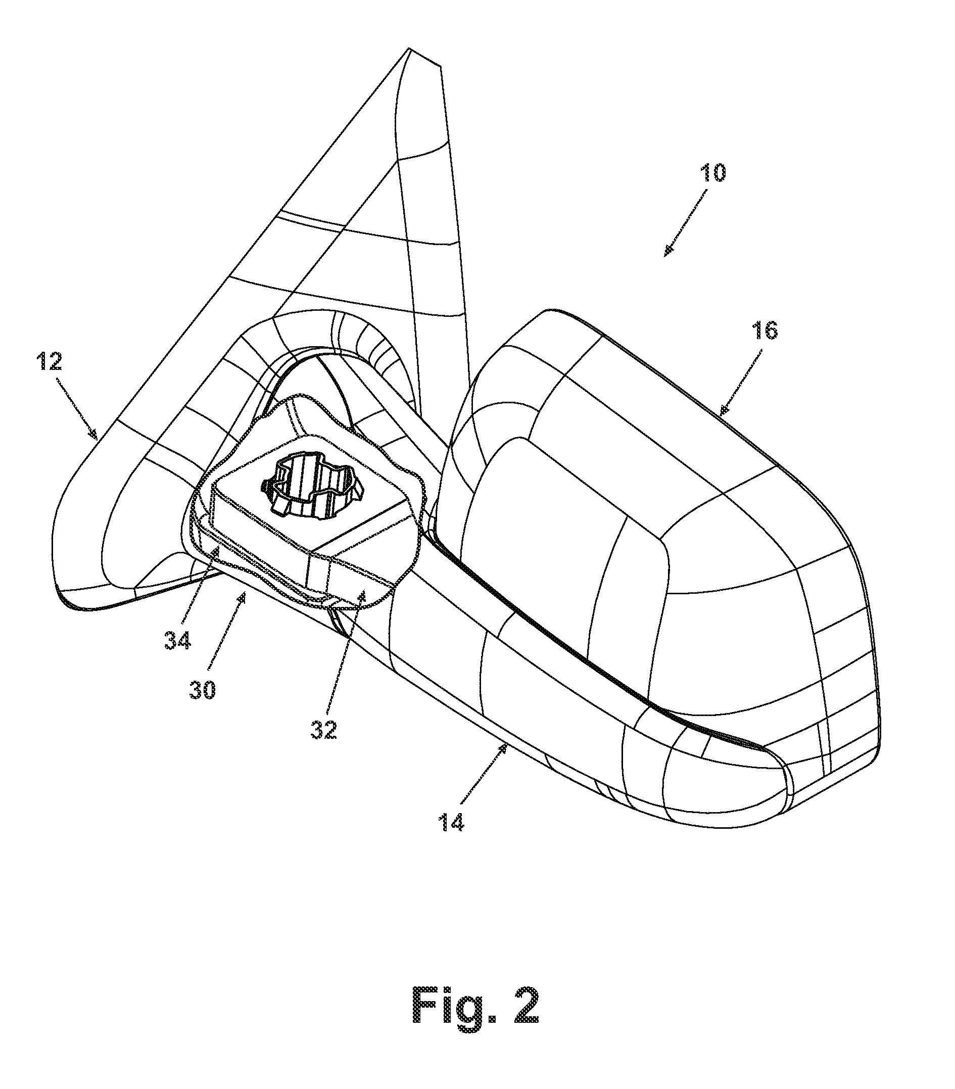
[0035]FIG. 2 illustrates the external vehicular mirror system 10 with a pivot connection 30 comprising a support arm portion 32 and a base portion 34 in cooperative disposition as hereinafter described. It should be understood that the pivot connection 30 is disposed in the mirror system so that the base portion 34 is immovably attached to or integrated into the base 12, and the support arm portion 32 is attached ...

third embodiment

[0042]FIGS. 12-24 illustrate the invention comprising a pivot assembly 100 adapted for incorporation into a vehicular mirror system 10 similar to that illustrated in FIG. 1. As illustrated in FIGS. 12 and 13, the pivot assembly 100 comprises a support arm 102 and a base frame 104. The support arm 102 has a distal end 106 adapted for attachment of a tilt actuator and reflective element assembly (not shown), and a proximal end 108 adapted for attachment to the base frame 104. The proximal end 108 terminates in an arcuate wall 110. A pivot opening 112 extends through the support arm 102 for attachment to the base frame 104, as hereinafter described.

[0043]The base frame 104 has a distal end 114 and a proximal end 116. The proximal end 116 is adapted for attachment to a motor vehicle in a generally well known manner. The proximal end 116 terminates distally in an arcuate wall 120. Extending from the arcuate wall 120 to the distal end 114 is a generally planar pivot floor 118. Extending g...


PUM


Abstract

A vehicular exterior rearview mirror system comprises a reflective element assembly, a base frame coupling the reflective element assembly to a vehicle, a support arm for coupling the reflective element assembly to the base frame, and a pivot connection for pivotally coupling the support arm to one of the base frame and the reflective element assembly. The pivot connection comprises a pedestal having at least two detent ribs, and an opening for receipt of the pedestal therethrough having at least two detent channels. Pivoting of one of the support arm relative to the base frame and the reflective element assembly relative to the support arm moves a first one of the at least two detent ribs out of a first one of the at least two detent channels and into a second one of the at least two detent channels.

Description

CROSS-REFERENCE TO RELATED APPLICATION[0001]This application claims the benefit of U.S. provisional application Ser. No. 60 / 596,908, filed Oct. 28, 2005, which is incorporated herein in its entirety.BACKGROUND OF THE INVENTION[0002]1. Field of the Invention[0003]The invention relates generally to rearview mirrors for motor vehicles and more particularly to a pivot connection for a vehicular rearview mirror comprising only two mating elements in a snap-fit relationship.[0004]2. Description of the Related Art[0005]External rearview mirrors are ubiquitous for conventional motor vehicles. Such mirrors are frequently adapted to be adjusted by the vehicle operator at preselected positions. For example, external rearview mirrors can be selectively folded against the vehicle when not in use, and unfolded away from the vehicle for use. The mirrors can also be extended laterally away from the vehicle (the “outboard” position) to adjust the rearward view during towing of a trailer, and retract...

Claims


Application Information

Patent Timeline
Patent Type & Authority Patents(United States)
IPC IPC(8): G02B7/182B60R1/06
CPCB60R1/06B60R1/076
Inventor FOOTE, KEITH D.RUSE, JAMES A.
Owner MAGNA MIRRORS OF AMERICA INC
Learn More